Below is a description and log of the journey that I took to create this solution:
(Read the French Translation by David Brunet)
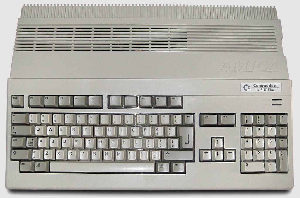
I owe my career to the Amiga, specifically the A500+ that my parents purchased for me for Christmas at the age of 10. At first I played the games, but after a while I started getting curious about what else it could do. I played with the Deluxe Paint III and learnt about Workbench.
The Amiga 500 Plus:
Every month I purchased the popular Amiga Format magazine. One month had a free copy of AMOS. I entered the Amiga Format Write A Game In AMOS competition when AMOS Professional was put on a cover-disk later, and was one of the 12 (I think) winners with In The Pipe Line. You really had to chase them for prizes though!
AMOS - The Creator!:

Moving on, I used the Amiga as part of my GCSEs and A-Level projects (thanks to Highspeed Pascal, which was compatible with Turbo Pascal on the PC)
Anyway, that was a long time ago, and I have boxes of disks, and an A500+ that doesn’t work anymore, so I thought about backing those disks up onto my computer, for both preservation and nostalgia.
The Amiga Forever website has an excellent list of options that include hardware, and abusing two floppy drives in a PC - Sadly none of these were an option with modern hardware, and the KryoFlux/Catweasel controllers are too expensive. I was really surprised that most of it was closed source.
Massively into electronics and having played with Atmel devices (AT89C4051) whilst at University I decided to take a look at the Arduino (credit to GreatScott for the inspiration showing just how easy it is to get started) I wondered if this was possible.
So I Googled for Arduino floppy drive reading code, and after skipping all of the projects that abused the drive to play music, I didn’t really find any solutions. I found a few discussions in a few groups suggesting it wouldn’t be possible. I did find a project based around an FPGA which was very interesting reading, but not the direction I wanted to go, so the only option was to build a solution myself.
When I started this project I hadn’t got a clue how the floppy drive worked, and even less how the data was encoded onto them. The following websites were invaluable in my understanding on what happens and how they work:
Based on the research I now knew theoretically how the data was written to the disk, and how the disk spun.
I began to work out some numbers. Based on the speed the double density disk rotated at (300rpm) and the way the data is stored (80 tracks, 11 sectors per track and 512 bytes per sector, encoded using MFM), to read the data accurately I needed to be able to sample the data at 500Khz; that’s quite fast when you consider the Arduino is only running at 16Mhz.
In the attempts that follow I’m only talking about the Arduino side. Jump to decoding.
First I needed to gather the hardware and interface to the floppy drive. The floppy drive I took from an old PC at work, and grabbed its IDE cable at the same time.
Below is a photo of liberated floppy drive from an old PC:
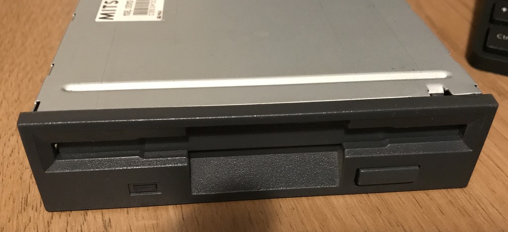
Studying the pin-out of the drive I realised I only needed a few of the wires from it, and after looking at the drive I realised it didn't use the 12v input either.
Getting the drive spinning was achieved by selecting the drive and enabling the motor. Moving the head was simple. You set the /DIR pin high or low, and then pulsed the /STEP pin. You could tell if the head had reached track 0 (the first track) by monitoring the /TRK00 pin.
I was curious about the /INDEX pin. This pulses once each rotation. As the Amiga doesn't use this to find the start of the track I didn't need it and could ignore it. After this its just a matter of choosing which side of the disk to read (/SIDE1) and connecting up /RDATA.
With the high data rate requirement my first thought was to find a way to make this less of an issue by trying to reduce the requirements on this rate.
The plan was to use two 8-bit shift registers (SN74HC594N) to reduce the required sampling frequency by a factor of 8. I used was what Ebay called Pro Mini ATmega328 Board 5V 16M Arduino Compatible Nano (so I don't know what that is officially, but this does work on the Uno!) to buffer this parallel data and send it to the PC using it’s serial/USART interface. I knew this needed to be running faster than 500K baud (with all of the serial overhead involved too).
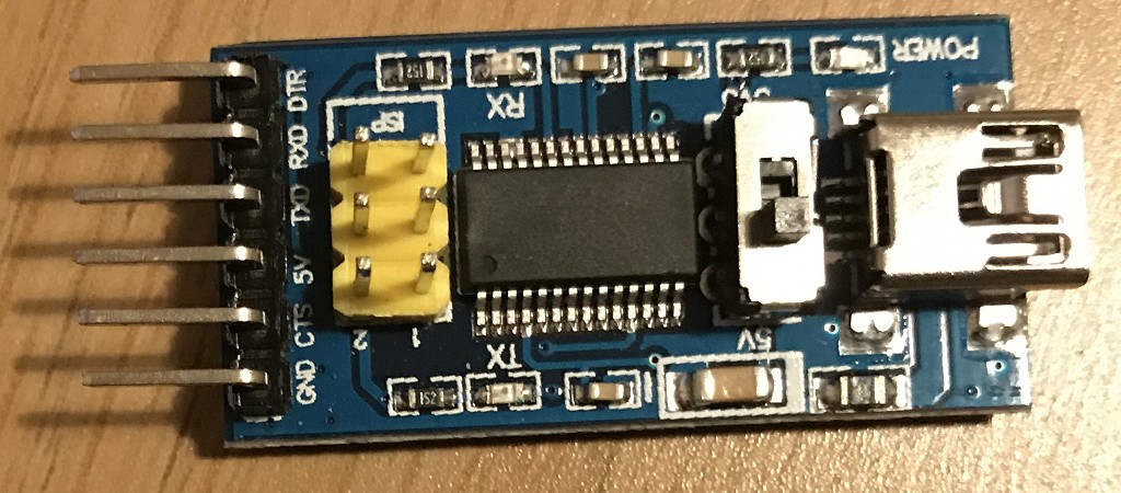
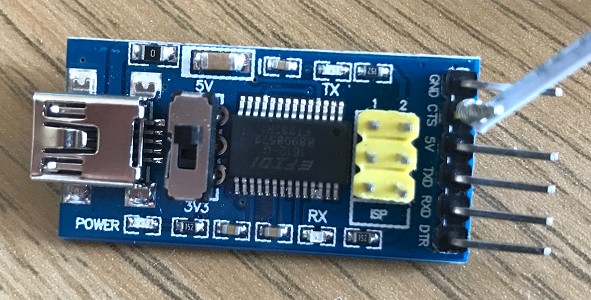
After ditching the standard Arduino serial library, I was really pleased to find I could configure the USART on the Arduino at up-tp 2M baud, and with one of those F2DI break-out boards (ebay called it Basic Breakout Board For FTDI FT232RL USB to Serial IC For Arduino - see below) I could happily and send and receive data at this rate (62.5Khz) but I needed to do this accurately.
The FTDI breakout board that perfectly fits the interface on the Arduino board:
First I used the arduino to setup on of the 8-bit shift registers only one of the 8 bits clocked high. The other received a feed directly from the floppy drive (thus providing serial to parallel conversion).
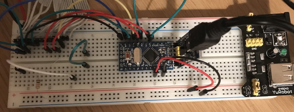
The following is a crazy picture of the breadboard I built this on at the time:
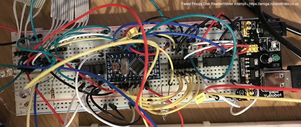
I used one of the Arduino's timers to generate a 500Khz signal on one of its output pins and as the hardware manages this it is very accurate! - Well, my multimeter measured it as exactly 500khz anyway.
The code worked, I clocked in a full 8-bits of data at 62.5khz, leaving the Arduino CPU hardly utilized. However I wasn’t receiving anything meaningful. At this point I realised I needed to take a closer look at the actual data coming out of the floppy drive. So I purchased a cheap old Oscilloscope from Ebay (Gould OS300 20Mhz Oscilloscope) to check out what was going on.
Whilst waiting for the oscilloscope to arrive I decided to try something else.
A fragment of code used to read the data from the shift registers:
void readTrackData() {
    byte op;

    for (int a=0; a<5632; a++) {
        // We'll wait for the "byte" start marker
        while (digitalRead(PIN_BYTE_READ_SIGNAL)==LOW) {};
        // Read the byte
        op=0;
        if (digitalRead(DATA_LOWER_NIBBLE_PB0)==HIGH) op|=1;
        if (digitalRead(DATA_LOWER_NIBBLE_PB1)==HIGH) op|=2;
        if (digitalRead(DATA_LOWER_NIBBLE_PB2)==HIGH) op|=4;
        if (digitalRead(DATA_LOWER_NIBBLE_PB3)==HIGH) op|=8;
        if (digitalRead(DATA_UPPER_NIBBLE_A0)==HIGH) op|=16;
        if (digitalRead(DATA_UPPER_NIBBLE_A1)==HIGH) op|=32;
        if (digitalRead(DATA_UPPER_NIBBLE_A2)==HIGH) op|=64;
        if (digitalRead(DATA_UPPER_NIBBLE_A3)==HIGH) op|=128;

        writeByteToUART(op);

        // Wait for high to drop again
        while (digitalRead(PIN_BYTE_READ_SIGNAL)==HIGH) {};
    }
}
I decided that the shift registers, whilst a nice idea probably weren’t helping. I was able to easily read 8 bits in one go, but it occurred to me that I couldn’t be sure that all of the bits were clocked in correctly in the first place. Reading the documentation it suggested that the data were more of short pulses rather than highs and lows.
I removed the shift registers and wondered what would happen if I tried to check for a pulse from the drive in an Interrupt (ISR) using the previously setup 500Khz signal. I reconfigured the Arduino to generate the ISR, and after I got passed the issues of the Arduino libraries getting in the way (using the ISR I wanted) I moved to Timer 2.
I wrote a short ISR that would shift left a global single byte by one bit and then if the pin connected to the floppy drive data line was LOW (the pulses are low-going) I would OR a 1 onto it. Every 8 times I did this I wrote the completed byte to the USART.
This didn't go as expected! The Arduino started to behave very erratically and strange. I soon realised the ISR was taking more time to execute than than the time between calls to it. (I could receive a pulse every 2µSec and based on the speed of the Arduino and making a wild assumption that every C instruction translated to 1 clock machine code cycle I realised I could at most have 32 instructions. Sadly most would be more than one instruction, and after Googling I realised the overhead on starting an ISR was massive anyway. Not to mention the digitalRead functions being very slow.
I ditched the digitalRead function in favour of accessing the port pins directly! This still didn’t help and wasn’t fast enough. Not prepared to give up, I shelved this approach and decided to move on and try something else.
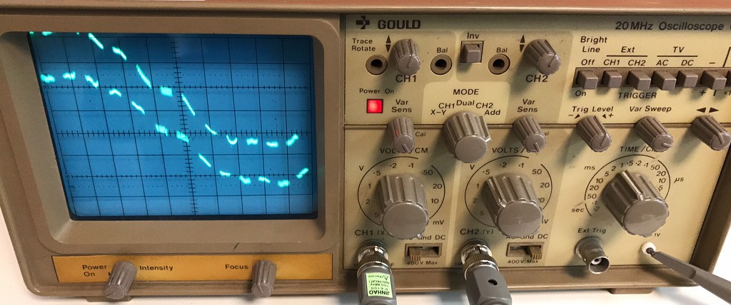
At this point the oscilloscope that I purchased arrived, and it worked! A crusty old Oscilloscope that was probably older than me! But still did the job perfectly. (If you don’t know what n Oscilloscope is check out EEVblog #926 - Introduction To The Oscilloscope, and if you're into electronics then I suggest watching a few more and having a browse around the EEVBlog website.
My newly purchased crusty old Oscilloscope (Gould OS300 20Mhz):
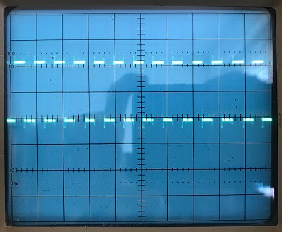
After connecting the 500Khz signal to one channel and the output from the floppy drive to another it was obvious something wasn’t right. The 500Khz signal was a perfect square wave using it as a trigger, the floppy data was all over the place. I could see the pulses, but it was more of a blur. Likewise if I triggered from the floppy drive signal, the 500Khz signal square wave signal was all over the place and not in sync with it.
Photos of the traces on the oscilloscope triggering off of the two channels. You cant quite see it, but on the channel not being triggered is thousands of faint ghostly lines:
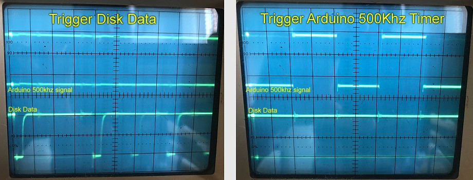
Individually I could measure pulses from both signals at 500Khz, which didn’t make sense, as if they ere both running at the same speed but won’t trigger so you can see both signals properly then something must be wrong.
After a lot of playing with the trigger levels I managed to work out what was going on. My signal was a perfect 500Khz, but looking at the floppy drive signal, well they were spaced correctly, but not all the time. Between groups of pulses there was an error drift, ans also gaps in the data that put the signal totally out of sync.
Remembering the previous research, the drive was supposed to rotate at 300rpm, but it might not actually be exactly 300rpm, plus the drive that wrote the data might also not be at exactly 300rpm. Then there is the spacing between sectors and sector gaps. Clearly there was a synchronisation issue, and synchronising the 500Khz signal to the floppy drive at the start of a read wasn’t going to work.
I also discovered that the pulse from the floppy drive was extremely short, although you could modify this by changing the pullup resistor, and if the timing was not exactly right then the Arduino might miss a pulse all together.
When I was at university (University of Leicester) I took a module called embedded system. We studied the Atmel 8051 micro-controllers. One of the projects involved counting pulses from a simulated weather station (rotary encoder). Back then I sampled the pin at regular intervals, but this wasn't very accurate.
The module lecturer, Prof Pont suggested that I should have used the hardware counter features of the device (I didn’t even know it had one the time.)
I checked the datasheet for the ATMega328 and sure enough each of the three timers could be configured to count pulses triggered from an external input. This meant speed was no longer an issue. All I actually needed to know was if a pulse had occurred within a 2µSec time window.
I adjusted the Arduino sketch to reset the 500khz timer when the first pulse was detected and each time the 500khz timer overflowed I checked the counter value to see if a pulse had been detected. I then performed the same bit-shifting sequence and every 8 bits wrote out a byte to the USART.
Data was coming in and I started to analyse it on the PC. In the data I started to see what looked like valid data. The odd sync word would appear, or groups of 0xAAAA sequences, but nothing reliable. I knew I was on to something, but was still missing something.
I realised that as the data was being read, the data from the drive was probably going out of sync/phase with my 500khz signal. I confirmed this by just reading 20 bytes each time I started reading.
Reading up about how to handle this sync issue I stumbled across the phrase Phase Locked Loop or PLL. In very simple terms, for what we are doing, the phase locked loop would dynamically adjusts the clock frequency (the 500khz) to compensate for frequency drift and variance in the signal.
The resolution on the timer wasn't high enough to vary it by small enough amounts (eg: 444khz, 470khz, 500khz, 533khz, 571khz etc) and to perform this properly I would probably need the code to run a whole lot faster.
The Arduino timers work by counting up to a predefined number (in this case 16 for 500khz) then they set an overflow register and start again from 0. The actual counter value can be read and written to at any point.
I adjusted the sketch to wait in a loop until the timer overflowed, and when it overflowed I checked for a pulse as before. The difference time time was that when a pulse was detected inside the loop I reset the timer counter value to a pre-defined phase position, effectively resynchronising the timer with each pulse.
I chose the value I wrote to the timer counter such that it would overflow at 1µSec from the detection pulse (half way) so that next time the timer overflowed the pulse would have been 2µSec apart.
This worked! I was now reading almost perfect data from the disk. I was still getting a lot of checksum errors which was annoying. I resolved most of these by continuously re-reading the same track on the drive until I had all 11 sectors with valid header and data checksums.
I was curious at this point, so I hooked it all back up to the oscilloscope again to see what was going on now, and as I guessed, I could now see both traces as they were both staying in sync with each other:
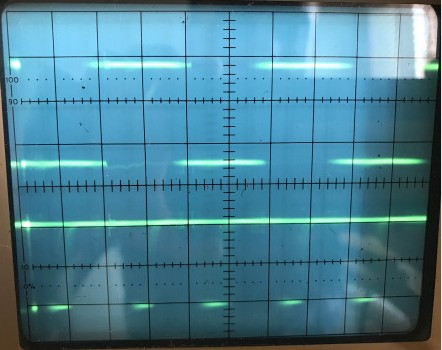
I would love to see this a little clearer, if anyone wants to donate me a lovely top of the range digital oscilloscope (eg one of them Keysight ones!) I would really appreciate it!
I wondered if I could improve on this. Looking at the code, specifically the inner reading loop (see below) I had a while loop waiting for the overflow and then an inner if looking for a pulse to sync to.
A fragment of code used to read the data and sync to it:
register bool done = false;

// Wait for 500khz overflow
while (!(TIFR2&_BV(TOV2))) {
    // falling edge detected while waiting for the 500khz pulse.
    if ((TCNT0) && (!done)) {
        // pulse detected, reset the timer counter to sync with the pulse
        TCNT2=phase;

        // Wait for the pulse to go high again
        while (!(PIN_RAW_FLOPPYDATA_PORT & PIN_RAW_FLOPPYDATA_MASK)) {};

        done = true;
    }
}

// Reset the overflow flag
TIFR2|=_BV(TOV2);

// Did we detect a pulse from the drive?
if (TCNT0) {
    DataOutputByte|=1;
    TCNT0=0;
}
I realised that depending on which instruction was being executed in the above loops, the time between pulse detection and writing TCNT2=phase; could change by the time taken to execute a few instructions.
Realising that this may be causing some errors/jitter in the data and also with the above loop it is possible I might actually miss the pulse from the drive (thus missing a re-sync bit) I decided to take trick from one of my earlier attempts, the ISR (interrupt).
I wired the data pulse to a second pin on the Arduino. The data was now connected to the COUNTER0 trigger and now also the INT0 pin. INT0 is one of the highest interrupt priorities so should minimise the delays between trigger and the ISR being called, and as this is the only interrupt I am actually interested in al of the others are disabled.
All the interrupt needed to do was perform the re-sync code above, this changed the code to look like this:
// Wait for 500khz overflow
while (!(TIFR2&_BV(TOV2))) {}

// Reset the overflow flag
TIFR2|=_BV(TOV2);

// Did we detect a pulse from the drive?
if (TCNT0) {
    DataOutputByte|=1;
    TCNT0=0;
}
The ISR looked like this: (note I didn't use attachInterrupt as this also adds overhead to the call)
volatile byte targetPhase;

ISR (INT0_vect) {
  TCNT2=targetPhase;
}
But compiling this produced far too much code to execute fast enough. In fact disassembling the above produced:
push r1 push r0 in r0, 0x3f ; 63 push r0 eor r1, r1 push r24 lds r24, 0x0102 ; 0x800102sts 0x00B2, r24 ; 0x8000b2 <__TEXT_REGION_LENGTH__+0x7e00b2> pop r24 pop r0 out 0x3f, r0 ; 63 pop r0 pop r1 reti
By analysing the code I realised there were only a few instructions I actually needed. Noting that the compiler would keep track of any registers I bashed I changed the ISR as follows:
volatile byte targetPhase asm ("targetPhase");

ISR (INT0_vect) {
  asm volatile("lds __tmp_reg__, targetPhase");
  asm volatile("sts %0, __tmp_reg__" : : "M" (_SFR_MEM_ADDR(TCNT2)));
}
Which disassembled, produced the following instructions:
push r1 push r0 in r0, 0x3f ; 63 push r0 eor r1, r1 lds r0, 0x0102 ; 0x800102sts 0x00B2, r0 ; 0x8000b2 <__TEXT_REGION_LENGTH__+0x7e00b2> pop r0 out 0x3f, r0 ; 63 pop r0 pop r1 reti
Still too many instructions. I noticed that the compiler was adding a lot of extra instructions, that for my application really didn't need to be there. So I looked up the ISR() and stumbled upon a second parameter ISR_NAKED. Adding this would prevent the compiler from adding any special code, but then I would be responsible for maintaining registers, the stack and returning from the interrupt correctly. I also would need to maintain the SREG register, but as none of the commands I needed to call modified it I didn't need to worry about it.
This changed the ISR code to become:
ISR (INT0_vect, ISR_NAKED) {
  asm volatile("push __tmp_reg__");                                         // Preserve the tmp_register
  asm volatile("lds __tmp_reg__, targetPhase");                             // Copy the phase value into the tmp_register
  asm volatile("sts %0, __tmp_reg__" : : "M" (_SFR_MEM_ADDR(TCNT2)));       // Copy the tmp_register into the memory location where TCNT2 is
  asm volatile("pop __tmp_reg__");                                          // Restore the tmp_register
  asm volatile("reti");                                                     // And exit the ISR
}
Which the compiler converted to:
push r0 lds r0, 0x0102 ; 0x800102sts 0x00B2, r0 ; 0x8000b2 <__TEXT_REGION_LENGTH__+0x7e00b2> pop r0 reti
Five instructions! Perfect, or at least as fast as it was going to be, theoretically taking 0.3125µSec to execute! This should now mean the re-sync should happen at time-consistent periods after the pulse. Below is a timing diagram of what is going on. This is how you recover data from a serial data feed that doesn't have a clock signal:
This improved the results a little. It’s still not perfect. Some disks read perfectly every time, some disks it takes ages and has to keep retrying. I am unsure if this is because some of the disks have been sitting there for so long that the magnetism has degraded to such a low level that the drives amplifiers can't cope with it. I wondered if this was something to do with the PC floppy disk drive, so I connected this up to an external Amiga floppy disk drive I had, but the results were identical.
I wondered if there was anything else that could be done. Perhapses the signal from the drive was more noisy than I thought it had been. After reading further information I discovered that a 1KOhm pullup resistor was the norm, fed into a Schmitt trigger.
After installing an SN74HCT14N Hex Schmitt Trigger and reconfiguring the sketch to trigger on rising edges instead of falling edges I gave it a try, but it didn't really make any notable difference. I guess as I was looking for one or more pulses each time this probably absorbed any noise anyway. So we'll stick method Attempt 5!
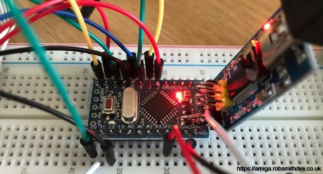
My final breadboard solution looked line this:
Note the wiring on the above is slightly different to the live sketch. I re-ordered some of the Arduino pins to make the circuit diagram easier.
I was a little dissatisfied with some of the disks I had not reading. Some times the disks just didn't sit correctly in the floppy drive. I guess the spring on the shutter wasn't helping.
I started looking at detecting if there were any errors in the actual received MFM data from the disk.
From the rules of how MFM encoding works, I realised that a few simple rules could be applied as follows:
Firstly when decoding MFM data I looked to see if there were two '1's in a row. If they were I assumed that the data had got a little blurred over time and ignored the second '1'.
With this rule applied, there are literally three situations of 5 bits where errors are left to occur. This would be a new area where I could look to improve the data.
Mostly though I was surprised, there really weren't that many MFM errors detected. I am a little confused why some of the disks won't read when no errors are found.
This is an area for further investigation.
After reading how MFM worked, I wasn’t entirely sure how it aligned correctly.
At first I thought that the drive output 1s and 0s for the on and off bits. This wasn’t the case. The drive outputs a pulse for every phase transition, ie: every time the data went from 0 to 1, or 1 to 0.
After reading this I wondered if I needed to convert this back into 1’s and 0s by feeding it into a flip-flop toggle, or read the data, search for sectors, and if none were found then invert the data and try again!
It turns out this isn’t the case and it’s much simpler. The pulses are actually the RAW MFM data and can be fed straight into the decoding algorithms. Now I understood this I started writing code to scan a buffer from the drive and search for the sync word 0x4489. Surprisingly I found it!
From the research I had conducted, I realised I needed to actually search for 0xAAAAAAAA44894489 (a note from the research also suggested that there were some bugs in early Amiga code that meant that the above sequence wasn’t found. So instead I searched for 0x2AAAAAAA44894489 after ANDing the data with 0x7FFFFFFFFFFFFFFF).
As expected I found up to 11 of these on each track corresponding to the actual start of the 11 Amiga sectors. I then started to read the bytes that followed to see if I could decode the sector information.
I took a snippet of code from one of the above references to help with MFM decoding. No point in re-inventing the wheel eh?
After reading the header and data, I tried writing it to disk as an ADF file. The standard ADF file format is very simple. It is literally just the 512 bytes from each sector (from both sides of the disk) written in order. After writing it and trying to open it with ADFOpus and got mixed results, sometimes it opened the file, sometimes it failed. There were obviously errors in the data. I started to look at the checksum fields in the header, rejecting sectors with invalid checksums and repeating reading until I had 11 valid ones.
For some disks this was all 11 on the first read, some took several attempts and different phase values too.
Finally I managed to write valid ADF files. Some disks would take ages, some literally the speed the Amiga would have read them. Not having a working Amiga anymore I couldn’t actually check if these disks read properly normally, they’ve been stored in a box in the attic for years so may well have degraded.
So after successfully being able to read disks I figured if you want to keep the original physical medium you might want to write disks back again. I figured I'd work this out in reverse, starting with the software (ie: converting the ADF disk files into MFM data for the interface to write somehow)
So I started by adding classes to read an ADF disk, and encode all the sectors as one track. Knowing I could potentially test the data I created by feeding it back into the decoding part, I started work on this. While working on this I decided to try to find out what was wrong with my Amiga. After-all, I can't test any disks I create if I don't have anything real to test them on.
Taking my A500+ apart I noticed it had suffered one of the most common problems, the clock battery had leaked everywhere. So I de-soldered this from the board and set about cleaning the board up. Whilst at it I pulled the entire machine out and set about cleaning up 20 years of dust and grime. I even took the floppy drive apart to clean it.
Whilst cleaning it I decided it was time to get rid of the yellowing, so followed the information about Retr0brite and tried it.
I then checked all of the joints on the main motherboard and found a lose connection by the power connector, a few touchups with the soldering iron and as good as new. I waited until I was happy with the Retr0brite process before reassembling the computer
Meanwhile I continued working on the code for writing disks. I wanted to read the status of the write protect line, but no matter what I set it to it didn't seem to change voltage. So I pulled the drive apart and followed the traces from the little switches that detect the write protect status to a little IC. At this point I guessed that the output is probably only available when you actually want to write data.
After a lot of experimentation I found that you needed to pull the /WRITE_GATE pin LOW before spinning up the drive to enable writing. At this point you could obtain the write protect status. I also noticed that while the /WRITE_GATE was low the drive didn't switch back off like it used to until that pin had returned to its default HIGH state.
The Amiga would write an entire track in one go. A track in memory is 11*512 bytes (5638 bytes), however, after MFM encoding and putting in correct AmigaDOS format, the track works out as 14848 bytes. Well, there's no way that can fit in the Arduino's 2k of memory, nor its 1k of EEPROM. I needed an alternative method.
I decided I would try to send the data 1 byte at a time in a high priority thread and wait for a response byte from the Arduino before sending the next. I changed the baud rate to 2M to reduce the lag between characters. This meant that it took roughly 5.5uS to send each character, and 5.5uS to receive one back. The Arduino would need to write out 8 bits, at 500khz, so would need a new byte every 16uS. So there should be time, assuming the code loop is tight enough and the operating system doesn't delay the sending and receiving too much.
This was a complete utter failure. The entire read/write cycle took far too long, well beyond one revolution of the disk. The Arduino side was probably fast enough, but the OS wasn't responsive enough. Reading disks works because the OS (Windows in my case) would buffer the data coming in, but writing, Windows would just send it all in one go, but because of the rate I'm sending at is far faster than the Arduino needs it data would be lost. This was why I decided on this two-way acknowledgement process
Software flow control for this application was just not fast enough. I decided to investigate hardware flow control. I noticed on the FTDI breakout board there are CTS and DTR pin. These stand for Clear To Send and Data Terminal Ready. I noticed that while the breakout board was connected, the Arduino board connected the CTS to GND.
FTDI breakout board with CTS pin bent out and a wire attached
I also didn't know which direction these pins were actually in, but after some experimentation, I found the CTS pin could be signalled from the Arduino and used by the PC to control the flow. Normally this is done using a circular buffer, but in my case I couldn't allow this, so I simply set it to '1' when I don't want data, and '0' while I do.
This now meant I could just ask the OS to bulk send the bytes as one chunk, and hope that it was all handled at the kernel level it wouldn't get interrupted.
I had an inner loop that output each bit from the 8 bits but decided it was probably better timing wise to unravel it into 8 sets of commands instead.
This didn't work. If I allowed the code to run without actually running the disk writing part then all bytes were received correctly, with running the code it didn't and bytes being received were being lost.
I suspected that changing the status of the CTX line didn't instantly stop the flow of data and the computer may still send a character or two. Possibly by the time I had signalled the CTX line it was already in the process of sending the next character.
I didn't want to have a serial interrupt as I didn't want any of the writing timings to be distorted. I realised that in-between writing each bit to the floppy drive there would be a number of CPU cycles sitting in the next while loop. I decided to check between each bit write if another byte had been received since CTX went high and store it.
My theory was that when you raised CTX the computer was probably already in the middle of transmitting the next byte and as you can't stop it mid-stream then it would half after this one. This means I only need to check for one extra byte during the loop and use it if found instead of looking at the serial port again.
So this seemed to work, and the Arduino completed the write without losing any data from the computer. The only questions now was, has it actually written any data, and if so, is any of it valid!
At this point I had only encoded one track, so I decided to run the entire algorithm to encode all 80 tracks. Something strange was happening. The drive head wasn't moving at all. It still did when reading, but not when writing.
I found that in order to move the drive head back and forth you first had to raise the /WRITE GATE pin, I suspected this was required for changing the surface also. Once I added code to do this the drive head moved as expected. This did make sense and would prevent accidental writing of tracks while moving the head around.
So at this point I wrote a disk image out I had created previously, and then tried to read it back. Nothing could be detected!. Either the data I had written was invalid, or the way I was writing it was wrong.
I decided to feed the encoded MFM sector data that I was creating into my sector decoding algorithm used by the reader to validate that what I was generating was correct ans valid, and it was. Something was obviously wrong with how I was writing the data to the disk.
As no data was being read correctly I decided try a few different approaches. I wasn't sure if the /WRITE DATA pin should be pulsed (and if so, by how long), toggled or just set to the raw data value. My current implementation pulsed the pin. I hadn't been able to find any information online about how the write pin was physically suppose to be manipulated when writing.
The read head would send us a pulse each time there is a flux reversal. I decided to change the implementation so that WRITE DATA was just set to the value of the bit. That didn't work either. So I changed the code to toggle the current state of the pin. Still no luck.
Clearly one of these approaches must have been the correct one. So I decided to get out the trusty Oscilloscope again to have a look at what was going on. I decided to write the MFM pattern 0xAA to to every byte on a track continuously. 0xAA in binary is B10101010, so this would give me a perfect square wave that I could monitor for the required frequency.
If it didn't see a perfect square wave at the desired frequency then I knew there must be some kind of timing issue.
I hooked up the scope, but was surprised to see the timings were perfect. However, being an old scope I couldn't see more than a few pulses. The scope had this wonderful x10 "mag" mode. When pressed it increased the time-base by 10, but more importantly allowed you to scroll through all of the data much like on a modern digital scope.
Something wasn't correct here. It looked like every 12 bits or so I ended up with a period of just "high".
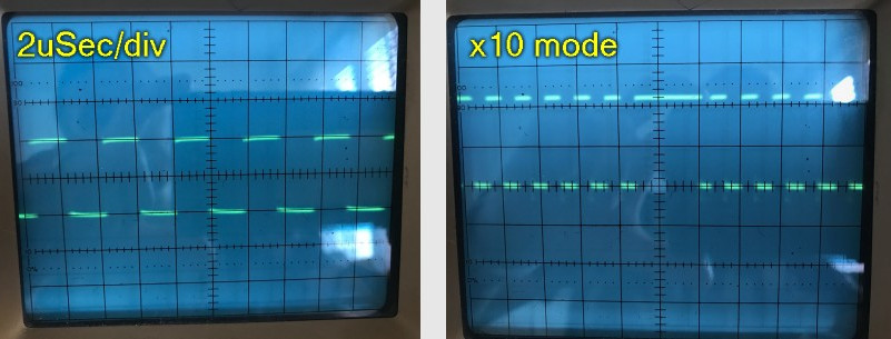
Either the data I was sending was in some way invalid, or there was something causing a pause in the writing process every 12 bits or so. 12 being a strange number considering there are only 8 bits in a byte.
After thinking about this I wondered if I was back with a flow control issue. The way I had designed the loop was to scoop up any stray extra bytes that were received after we had waited for one. But it wasn't intelligent enough to prevent the wait every other byte. I had two choices, move something into an interrupt, or patch the loop.
I decided to have a go at correcting the way the loop worked first. The issue was as a result of a delay caused by waiting for the next byte from the computer. If we lowered CTX and waited for a byte, by the time we raised CTX again another byte was already on the way.
I change the loop so that when the second byte received had been used the Arduino momentarily pulled CTS low and then high again to allow another character to be sent. This meant on the next loop we would have already received the next byte so no waiting was required.
Testing this produced a perfect square wave:
This meant all of the timing for writing a track was perfect, it was just down to the actual data that was being written. I decided to let this run for a few tracks and sides, and then read it back to see if it had written correctly. I was setting the /WRITE_DATA pin to the corresponding bit value from the data received.
When reading the data back it looked like nothing had been encoded, but then I skipped to the other side of the disk. Sure enough there was my pattern. I didn't know why it had only written to one side of the disk.
After some thinking I started to wonder if the /WRITE GATE pin didn't actually work the way I thought it did. It occurred to be that by pulling the pin low it may be enabling the erase head on the drive. If this was the case then I should only do this when I was actually writing or I might end up with noise on the disk as it spins and erases.
I changed all of the code so that the /WRITE GATE was only used when first starting the drive, and later only literally during the write loop. That worked! I was now writing data to both sides of the disk!
So I tried again with a real ADF disk image and let it complete. I then used the reader portion to see if I could read it back. It worked! but for some reason it took quite some time to read this disk back. I wasn't getting any MFM errors but it was struggling to find all of the sectors.
There's were two possibilities for me to look at now, firstly had the data actually written timely enough, and secondly would the disk actually work in a real Amiga!
Too excited with the idea that I might have actually written a disk I booted up the now working A500+ and put the disk in. Moments later the disk started booted, and then displayed the famous checksum error message. So I was writing something valid, but it wasn't consistent.
I decided that unless I could read the data back at a much more accurate rate then writing a disk was pointless.
I wanted to improve the reading quality as I wasn't happy with the current implementation. The current implementation didn't allow enough flexibility for the pulses to arrive at slightly odd times. I needed a new approach.
Firstly, I decided I was going to sync the reading to the /INDEX pulse. Not required by the Amiga, but may come in handy later on for me testing writing and reading.
Several people in the comments to the first half of this project suggested that I should be recording the timing between pulses rather than the method that I had implemented. The only issue with this was getting this data to the PC fast enough. If I was to send a byte for each bit then I could easily exceed the maximum 2M baud.
I decided that the best thing to do would be to try to make sense of the data a little. So I decided to let the counter I was using originally to free-run, right up to 255. I then put the code in a loop waiting for a pulse and that this point saw how much time had passed.
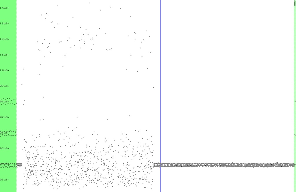
In an ideal situation the minimum value this would ever be would be 32 (corresponding to 2uS). With MFM you could only ever have a maximum of three 0's in a row, so the maximum this value should reach was 128. This meant there were a maximum of 4 possible combinations in a row.
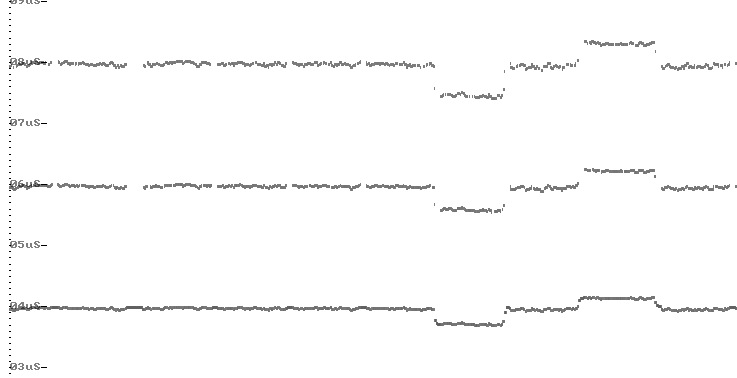
I sampled several disks to see where the majority of these frequencies lay, and the results can be seen below:
Looking at this, I find the majority of the points around a counter of 52, 89 and 120. However these were somewhat specific to my drive and therefor not a good guideline. After some experimentation I used the following formula: value = (COUNTER - 16) / 32. When clipped between 0 and 3 this gave me the output I required. Every 4 of these and I could write a byte out.
It occurred to me that because you couldn't have two '1's together in an MFM encoded bit stream I could safely assume anything for the first value was invalid and could be treated as another '01' sequence. The next part was to unpack this data once received by the PC and turn it back into MFM data. This was simple, since 00 couldn't happen, a 01 meant write '01', an 10 meant write '001' and a 11 meant write '0001'. I gave this a try and to my surprise my results were 100% successful. I tried with a few more disks too, 100%! I now had a very reliable disk reader.
With this new approach being a lot more tolerant on the data from the disk I no longer needed any phase analysis or as many retries. Most of my disks now read perfectly. Some required a few retries, but got there in the end. The last part was to statistically analyse the data and see if it could be repaired, however, 99% of the time bad data coming in was completely unrecognizable and so was little help.
Now that I could verify what I had written with high accuracy it meant testing the writer would be much easier.
I set about analyzing the code to see what was going wrong. I wrote a 0x55 sequence to an entire track and then read it back in. From time to time a bit had shifted in the data coming back meaning there was some kind of timing issue in writing.
It turned out that this was partly due to the way I was handling the serial port, and partly due to the use of the timer. I was waiting for the timer to reach the value 32, writing the bit, and then resetting it. I changed it so I didn't have to modify the timer counter value.
I would write the first bit when the counter reached 16, then the next when it reached 48 (16+32), and the next when it reached 80 (16+32+32) and so on. Timer2 being only 8-bit rolls over back to zero after the 8th bit, exactly when we needed it to. This meant that as long as we wrote the bit at the required timer value we would be at exactly 500kbps.
I also looked at how I was reading the data from the serial port. This was being read in-between each bit, but this needed to be as short as possible too. After a little experimentation I achieved the shortest working block.
After modifying the Windows code to support verify I was now ready to try again. This time I knew that if the disk verified properly then it should work properly in the Amiga.
So I tried writing another disk out. With verify it took longer. With the new algorithm about 95% of the tracks passed verification on the first go, with only the remaining 5% having to be re-written once more. I was happy with this and popped the disk into the Amiga. It worked perfectly!
After some feedback from some people who have been using this it was clear that even with verify on the drive wasn't always producing fully readable disks. The software could read them back perfectly, but the Amiga computers would report of a few checksum errors here and there.
I had another look at the code, wondered if it was a timing issue and looked to see if it could be made to be interrupt driven, but sadly with the small amount of time between each bit there simply isn't enough time with interrupts to achieve this with preserving the registers you modify etc.
I then looked back at the writing code. There is a small chance that after a full byte has written, the code could have looped back to start writing the next byte before the timer had overflowed back to 0, allowing the first bit to be written early.
I added a small loop to ensure this couldn't happen which hopefully will fix this for anyone having this issue.
I have had lots of feedback from people who have successfully made this project, both fully working and not working. I decided I would build a diagnostics module into the code to help anyone who can't get theirs to work.
The diagnostics option consists of a few extra commands for the Arduino to process as well as a whole series of events that get ran through to ensure everything is wired correctly.
After getting a lot of reports of of checksum errors for written disks I started to investigate. I thought at first I was going to have to get down to looking at the MFM data from the disk but the problem was actually much simpler
Looking at XCopy Pro to see the checksum errors, it reported codes 4 and 6 meaning checksum errors in the sector headers and data areas. If it had just been the data area then I would have assumed that it was purely something to do with writing the last few bits of the track, but it wasn't.
I started looking at the writing code and the padding I had around each track, wondering if I was overwriting the start of a track now and then, so I massively reduced the post-track padding from 256 bytes to 8. To my surprise my verify then kicked out a tonne of errors.
This made me wonder if the actual issue is I'm not writing enough data. I set about adding a Track Erase command to the Arduino which would write the 0xAA pattern to the entire track and then write my track afterwards. To my surprise XCopy gave it a 100% thumbs up. So hopefully that's cleared that problem up.
I've been out of this project for a while. But recently jumped back in to address some issues and merge some of the excellent things that others have done into this.
For example, there is a version that will read Commodore 1581 disks, as well as reading Atari HD disks
I'd been playing around with the idea that I didn't really understand why the timings i'd used for reading were what they were. Whilst they worked, the numbers didn't really follow an exact pattern, and didn't follow the ranges that they should.
I knew that there were three MFM bit patterns that should occur, 01, 001 and 0001. I had also seen 00001 which is technically not allowed. Ignoring the last one, these should take 64, 96 and 128uS. This would theoretically make the centre points (64-96) 80 and (96-128) 112. This is what I had. But it suddenly occurred to me that I was working with timings at the Arduino clock speed. This meant every instruction counts towards this.
I had one disk, with one track that always read with errors, but on an Amiga it read ok. It must have something to do with these timings as it seemed that the Amiga must be very tolerant of bit drift.
I started looking at the disassembled code, and the instructions involved. I was surprised to find that reading the value of the counter, and resetting it together took 4 clock ticks. So, I did some experiments with applying this offset to the timings used and to my surprise, the disk could now be read!
To tidy this up for future use, these are all calculated at the top of the code now.
One of the comments I heard while working on this project, was that people were surprised that writing worked as well as it did without what is known as write pre-compensation. After some background reading I was struggling to find out if it was even used on the Amiga, although you could see it was supported in the hardware.
The theory of write pre-compensation goes a little like this: Writing to the outer tracks, each time you send a '1' you cause a flux transition on the surface of the disk. This is like making tiny magnets on the surface of the disk. On the outer tracks this is fine, but as you get closer to the inner tracks these magnets get closer and closer together. Ignoring the details, you're suppose to adjust the timings slightly between bits to compensate for al of this, and also the time taken to build up the magnetic field.
Surprisingly there’s a fair amount of conflicting information about this, but the basis for this is to try to adjust the timings sightly to keep the '1' bits as far apart as possible without causing them to fall into another position.
The tricky part to all this, is the amount of pre-compensation, and when to use it. Some documents talk about applying it from track 40. Some say after track 79. Some say both and by different amounts.
The Amiga supports precomp of 0, 140, 280 and 560ns. Yes, nanoseconds. That's an incredibly small amount. The 16Mhz Arduino base clock is 62.5ns, so a mere 2 basic (like add) instructions would add up to 125ns. I wondered if we could even be that accurate with the resolution available.
I realised that there was no way this could be calculated on the Arduino, so it would need to be pre-calculated on the PC prior to being sent. I decided on some code, that would read the raw MFM bit-stream and convert it as follows:
| MFM Pattern | Binary Encoded As |
|---|---|
| 01 | 00 |
| 001 | 01 |
| 0001 | 10 |
| 00001 | 11 |
So, with this pattern I could send 4 of these sequences for each byte. But what about precomp. I needed to say for each sequence if the sequence should be EARLY (ie: -125ns), LATE (+125ns) or normal. Well there goes another two bits.
So, each nibble (nybble!?) (half a byte) now contained information regarding each sequence. But could I send this quick enough? Well. The baud rate is 2M, and roughly 10bits accounting for start and stop bits etc) which means each byte would arrive approx 5uS apart. According to what we learnt, that's roughly 88-90 Arduino clock ticks. On a good day, lets say 80 instructions. Sounds like plenty.
I needed to know this was going to work and be accurate. My trusty oscilloscope wouldn't be able to keep up with this, and even if it could, for the short amount of data it didn't have any storage options.
I decided upon a logic analyser but they're so expensive. Well, until I found the cheap clone knock off 24MHZ ones for about £10. And it worked very well. I was able to capture the data I was writing and accurately check the timings. Ok, with Nyquist sampling theory I really needed something like 32Mhz, but this was probably good enough.
I hooked it up, wrote some code to read this, set the timer to zero, and waited in a loop until it reached the required value based on 64 + (32 * pattern) +/- precomp. At first inspection, something very weird was going on. The sequence was there, but the data was shifting around all over the place. The pulses seemed to be shifting by approx +/- 180ns all over the place seemly random. Odd.
Then I remembered the issue I'd had with reading, and disassembled the code. The loop looked something like:
while (TCNT2 < value) {};
Looks harmless enough. But then it would be pulling the value from TCNT (2 clock ticks), then comparing it with another value. Another clock tick. Then jumping back if it wasn't the value. Another clock tick. This loop cost 4 ticks. That's quartering our resolution. How was I suppose to write something to a quarter of this with this method? Answer is you can't.
So I needed to find a faster way of monitoring the hardware counter, that was ticking at the speed of some of the instructions I was using. I knew that TCNT2 (Counter2/Timer2) could do a lot more than just count.
I started looking at the data sheet again for the ATMega328 chip. Its not for the feint of heart, but it does explain about every aspect of the micro-controller, from controlling pins, to the physical dimensions of the chips.
If you go to the section for the counters, there's a lot of other registers associated with them. Up-to now I hadn't really played with them, well, not since my very early experiments back when I started this journey.
There are registers that allow you to control the range it counts between (OCR2A & OCR2B), as well as bits in registers controlling how the timer operates. For example TCCR2A is used for controlling PWM output, or as I have it setup, no output.
Then there's its pair, TCCR2B, which up to now I have been using to set the counter speed, in this case to 'no pre-scaling' meaning run as fast as the oscillator is running (16Mhz).
You've also got TIMSK2 which is involved in enabling interrupts, and then finally TIFR2. Now that's an interesting register. Taking a closer look, there are three bits in it that you can read. OCF2B, OCF2A and TOV2. These 'bits' get set based on the rules setup in TCCR2A. For example, you can have these bits set when TCNT2 reaches the value of OCR2A, OCR2B or overflows back to zero.
I knew that merely reading from TCNT2 alone used 2 instruction cycles, but what about checking these bits. After disassembling the code I discovered they can be tested in a single instruction cycle. This meant the loop I used before could be replaced with something more like:
while (!(TIFR2 & bit(OCF2B)) {};
This loop would exit if I setup the above registers correctly when TCNT2 reached OCR2B. Fantastic. An interesting note. You have to write a '1' bit to these registers to clear them to zero. Don't ask. That's what the documentation says, and it's correct.
So I re-implemented the solution with this in mind. It was much better, but there was still lots of jitter. Part of the issue now, was to maintain writing to the disk I also needed to be reading the data from the serial port.
The code I was currently using to read the serial port and keep some buffered data looked like this:
if (UCSR0A & bit(RXC0)) {
	SERIAL_BUFFER[serialWritePos++] = UDR0;
	serialBytesInUse++;
}
The above piece of code, yet again, looks simple, but compiles down to around 14 instruction cycles! So when do I run this code? Once per 'bit'? Remember, we don't write any '0', we only write the '1's. So the minimum interval would be (theoretically) 64uS, max being 128uS. The data comes in around 1 byte every 80 uS. But we have to control this (this is what the CTS controls were for).
The micro-controller will buffer up-to two characters for you before data is lost. So it seemed that as long as I check once per cycle I should be ok. So this code was placed before the while loop.
Something weird happened. The PC finished sending all of the data and waited for the response. But the Arduino never sent one. The serial port, just has some interesting registers too. One of them will tell you if you haven't read the data quick enough. If you do
if (UCSR0A & (bit(FE0)|bit(DOR0))) break;Then your loop will exit if the serial port has a Data Over Run, or if the has been a Frame Error.
So, turns out, I was getting overrun errors. I wasn't reading the data quick enough, so the PC had sent all the data, but the Arduino had lost/overwritten some of the bytes before I had a chance to read them.
I couldn't put the above code in the while loop because it could potentially add a further jitter as the loop could potentially take over 14 clock cycles before testing again. So I decided to try something like this:
while (TCNT2<OCR2B-16) {
	if (UCSR0A & bit(RXC0)) {
		SERIAL_BUFFER[serialWritePos++] = UDR0;
		serialBytesInUse++;
	}
}
while (!(TIFR2 & bit(OCF2B)) {};
// Set the output to '0' at this point.  Wait a little, and then put it back to '1'.
I was switching the CTS line on and off only when there was or was not space in the buffer, and the theory with the above code, is allow up-to 16 clock cycles before the pulse to check for serial data, then stop and wait in the tighter loop and set the output. The output pulse, according to some of the drives needs to be something like 0.15 ~ 1.1uS. The, previous write method I was using they were 4us and it was fine, besides, its the falling edge (transition from 1 to 0) on the pulse that triggers the write, not the pulse being low its self!
Seemed like a good plan. But I was still getting issues, this time, namely my code was catching that I wasn't receiving enough data from the serial port quickly enough to keep my output buffer full. There's are 16 clock cycles sitting in the second loop not reading data from the serial port. If I reduce that number, then this issue went away, but the jitter came back.
At this point I almost gave up. I was so close, but just not good enough. I couldn't have any jitter, as if there was any then trying to use pre-compensation would be pointless anyway.
I needed a new approach. It was becoming obvious that me bit-banging out the data wasn't going to produce the level of accuracy I needed, well, not with this micro-controller. A faster one maybe.
I then thought back to my early experiments, and about the timers again. The could output waveforms, controlled at the hardware level usually for PWM. These would be a repeating pattern however. I wondered if there was a way I could use this information, a way I could vary these waveforms to produce what I needed getting it to do the accurate switching and me just programming it to do them.
What I really needed was a one-shot pulse. I.e: Start it running, after a specific time it would go low, stay there, and go back high again. But the Atmel micro-controller isn't designed to do this, or at least isn't suppose to be able to.
So I started researching it, I came across a trick which abused the AVR timer to create a one-shot pulse. Interesting. So I set about adapting this to what I needed. It essentially would set the timer up backwards so that it gets stuck after the pulse finishes. I doubt if this was ever intended, but the logic of the timers allows this to work!
So I set about changing the code to create the 01, 001, 0001 etc sequences using this one shot. I'd start it going at the first '0', and let it do the '1' pulse too. As the timer also works at 16Mhz, all I would need to do is offset where the pulse started to achieve precomp.
After some more analysis of the hardware registers for Timer2, I ended up setting them as follows:
TCCR2A = bit(COM2B1) | bit(WGM20) | bit(WGM21)| bit(WGM22);
TCCR2B = bit(WGM22) | bit(CS20);
TCCR2A: COM2B0 and COM2B1 combined according to the data sheet mean CLEAR OC2B when TCNT2 = OCR2B, and SET OC2B when TCNT2 reaches the bottom (being TCNT2=0). WGM20, WGM21, WGM22 state that we want to use Fast PWM mode.
TCCR2B: WGM22 enables waveform generation on the output pin associated, which for us, luckily, is the same pin we have been writing with, and CS20 is the precale=1 value we have used before.
The way the timer works, is when it hits BOTTOM (ie: 0) its suppose to reset TCNT2 back to the value of OCR2A. But if we set this to zero as well, the timer gets stick at 0 unless we manually change it.
All I now needed to do was work out the value of OCR2B, which is where we want the pulse to trigger at, and the initial value of TCNT2 to give the right amount of delay for that pulse.
Now, because the hardware was generating the pulse, it gave me more time to calculate the values and monitor the serial port, leaving it just until the last minute to accurately time the reset for the next sequence.
I ended up with some code like the following:
while (!(TIFR2 & bit(OCF2B))) {
	if (UCSR0A & bit(RXC0)) {
		SERIAL_BUFFER[serialWritePos++] = UDR0;
		serialBytesInUse++;
	}
};

while (!(TIFR2 & bit(TOV2)));

TCNT2 = counter;
OCR2B = pulseStart;
So, the first while loop would run until the pulse started, but we didn't actually need to generate the pulse, so we didn't care how accurate it was, and the second one accurately waits for the overflow condition (TCNT hitting BOTTOM).
After this, we immediately set TCNT2 (counter) to the delay for the new pulse, and write where the pulse should start from.
But there's a problem here. The second while loop also caused a little delay, plus writing to TCNT2 takes time. But this time, its all fixed, and as such we can compensate for it. I measured 6 clock cycles which accurately gave the correct timings.
Success! I confirmed in the logic analyser that the output was indeed what I needed, was timed very accurately, and that the pulse start was shifting back and forth by the 2 ticks that I wanted.
If you want to see exactly how this is done, then the code is up on GitHub, like the rest of the project. I was very pleased. At the start of this I wasn't sure this was even possible. I suspect that I would have been told its not possible, but using the hardware inbuilt components rather than doing the work myself made it possible.
This is a shortened summary. The actual process was a lot more infuriating debugging data at the bit-level seeing what I had done wrong and understanding how WinUAE implemented disk access.
I had the idea in the back of my mind of supporting the drive natively in Windows. This would involve device drivers for floppy disk access, and then file system drives to support the Amiga file system. This would be fantastic, and a lot of work.
I then got side-tracked with a thought that had come to mind a few times, and after receiving an email about it I decided to investigate further. Would it be possible to actually support this drive in WinUAE meaning you could use native Amiga disks in the emulator?
I had absolutely no idea, but couldn't see why not. I assumed, somewhere within the all that code it must be simulating a disk drive... somehow.... I assumed my approach would have to change some what, but as I'm sure you've seen, I'm not afraid of changing the code!
First step. Could I even compile the WinUAE source? Well Toni, who maintains it so excellently includes instructions on such things, and within minutes of downloading all the files it compiled and ran. I now just had to understand the code, and not surprisingly, there's a lot, and in a variety of styles, probably due to the nature of the project.
There's no reason that anyone probably looked into doing this before, and you could argue that there isn't any need. But I like a challenge. Toni had commented that he would have thought it would be difficult to synchronise the emulated Amiga timings with that of the a real spinning disk. I assumed he meant physically getting the disk MFM spin position to match where the emulator thought it was, but I had a plan.
Firstly, to support this the best I decided I needed to have more access to the floppy drive. Whilst it could work with the existing setup, it would be nice to be able to turn on and off the motor separate from other functions, and detect a disk being present in the drive. These are all available from the disk, I just hadn't needed them so they weren't connected up or right. There's a mod detailed for this in the hardware section. Its optional, each and highly recommended!
My plan was that if I could some how stream the data to the PC in time for WinUAE to read it, then all should be well. I'm not going to go into details here, but while that sounds simple enough the reality is far from simple.
Part of the problem is the data needs to be available to WinUAE when it wants it, and not when I have it ready. If I don't have the data and provide blank data you basically get read-errors. If however I force WinUAE to wait, the program will stutter and freeze (including the audio and mouse pointer) which is highly undesirable and unpleasant. This is not anyone's fault, this is just the pitfalls of what I'm trying to do.
Now, I can cache a full track read in memory, but I need to be sure it is an exact revolution without overlap or missing data, literally to the bit, which is no easy feat. But what do I get WinUAE to do while its caching it?
So first challenge. Read a complete track. Ah, that index pulse the drive generates, that'd gotta help. It does, but not to the level of accuracy I'd hoped. It could be my implementation, but I found its pulse jittered around a little. Not much, but just enough it wasn't reliable enough on its own.
So I settled for read the data until the pulse, carry on reading until the next pulse, and then try to match up the overlap. This worked surprisingly well, although wasn't anywhere near as trivial as I make it sound. This took several weeks to get working reliability making sure not to miss a single bit.
The downside is, the disk spins one revolution approx every 200ms. But I need to wait for the index marker first, which could be up to 200ms away if we're really unlucky. This means that at worse case, reading an entire track could take up to 400ms. We can't stop WinUAE for that long.
I wondered if it was possible, rather than to wait for the entire track, but to supply what we had so far, and then stall the process if necessary. Not good. It still stuttered too much to be acceptable.
I then had a thought. We're talking about physical hardware here, which doesn't work like its emulated counterpart. For example, when you switch the motor on to start the disk spinning, you can't read the data right away, you usually have to wait up to 750ms first. I know this, WinUAE knows this, and Kickstart knows this.
What about switching/stepping between tracks. Is there some dead time when the data from the drive isn't available or isn't considered stable? It turns out there is. Its usually up to about 18ms. Well, I still need to find up to another 382ms.
...or did I. I had a thought. What if, until the data was ready, I just kept feeding a '0' or a '1' back to WinUAE. There would be no pattern to lock onto, and no data, but because of the way WinUAE worked, it would still think a disk is present and spinning (it simulates the index pulse). Would it allow for a longer amount of dead time?
Turns out it does. I whacked this way way up to a maximum of 600ms before we potentially could stall WinUAE and everything was smooth. The data read, the mouse and music worked smoothly and a disk booted.
The data was being streamed from the Arduino in the background using a separate thread. I had setup a queue system whereby commands requesting changing the track number etc got queued, but we simulated a valid response back knowing the only important thing would be actually reading and writing to and from the disk.
Any command that was issued would immediately stop this streaming, but if left, would continuously read exact rotations from the disk, which WinUAE would switch in and out when it requested. My theory being that this may help support the 'weak bit' protection used in some games, but would also fix a potential read error that may have occurred.
So I had a disk reading successfully and, whilst not quite as fast as a real Amiga, it didn't seem to care. Even X-Copy didn't seem to care about this.
So now the challenge of writing occurred. Well, I now had the new Precomp writing code ready to go. So hopefully I could get this reliable too.
To cut this much shorter than it actually took, this was a absolute monster to get working. The main reason was for the way WinUAE handled the data it was trying to write. Data could get lost and I didn't know where the start of it was. So, instead I decided I would capture the data as its received from the amiga DMA write. It's what WinUAE was doing anyway, but I could receive it directly, and then, when finally the DMA request had completed I could just queue up a request to write it to disk.
This worked much better. The best test of this was to try and format a disk from within Workbench, after all it would also want to verify the results. Could any of my timing tricks work here too? Seemed so. I was now able to format a disk from Workbench, have it verified as it formatted it, and still play a MOD file solidly without any gaps in audio. Mission successful.
I wanted better support though, I have a few copy protected disks that still wouldn't boot. I suspected it was something to do with tricks of varying the bit-cell timings slightly to make some areas of the disk read quicker than others. A fairly common technique. I added code to the read streaming to tell if a bit was read normally, fast or slow, which I then simulated in WinUAE. Sadly this wasn't enough, so I guess that's as far as the Arduino board is going to go. I guess to those games, they still looked like pirate copies.
I had designed this interface with supporting other hardware too, after all, adding support for this hadn't been trivial and quite complex, not only the physical considerations, but actually figuring out what was going on in the emulator!
So the code was written with a set of common functions (abstract class) that needed to be implemented in order to support different hardware, which would make this far simpler in the future, and I still wanted to reach my goal of booting a copy protected game properly. I had two to try, the cheesy Captain Planet, and Lemmings, both of which came with the Cartoon Classics pack I got with the Amiga 500+, both that didn't work when you copied them, and both only booted so far and stopped on the copy in the same place they stopped when using them in WinUAE with my drive.
I don't like to give up. Happy that standard AmigaDOS disks would boot I turned my eyes to copy protection. I already knew a lot about what was going on, from short/long tracks, to weak/unformatted areas etc. My thought was that if I could read the data accurately enough then I didn't see why the emulator wouldn't play these games.
The problem was data. I had very limited bandwidth on the serial port from the Arduino. We're running at 2M baud, which (at 8 bits, 1 stop bit, and 1 start bit) means that we should be able to transmit one byte every 5uS. From the disk however, the shortest sequence being '01', could arrive at 4uS intervals. Sometimes even quicker depending on the speed of the drive we're using vs the one being written with.
So I first decided to look at the Lemmings disk I had. I knew it wouldn't boot if you copied it with XCopy, so knew something fishy was going on.
I added an extra command to the firmware for the Arduino which would give me (for a single revolution) a breakdown of timings for bit-cells found on a cylinder. There were obviously hot-spots around the 4uS, 6uS and 8uS intervals, as expected. But there were some tracks that had a lot more variation in them.
Now I knew that there were some tricks done with the data being recorded at slightly different bit-rates, the theory being that if you read the track and timed it, and compared it to another track you could measure the difference and detect the original vs the copy (as the copy would correct this slight timing inconsistency). We're talking very small difference here, if they were large the drive wouldn't read the data properly.
In the previous version I had tried to add a 'fast' and 'slow' option, but it didn't work. I needed something more sophisticated. Previously I had tried to state this speed per bit-cell, but did it really need to be that accurate?
I wondered what would happen if I averaged the timings over several patterns, and sent that to the pc, and used that to tell WinUAE to play the data slightly faster or slower. I knew it could do this, I had found some SCP recordings of these disks and they did boot, so knew it was possible.
The final format of this I ended up with was to send a byte back to the computer with the following information:
| Bits of one Byte | |||||||
|---|---|---|---|---|---|---|---|
| 7 | 6 | 5 | 4 | 3 | 2 | 1 | 0 |
| Index | Cell | Cell | Speed | ||||
Once added together, this number would go between 0 and 63, so we shift it right three (divide by 8) which gives us a number between 0 and 7, which nicely fits there. But would this be of high enough resolution to solve the problem.
Well, once presented back to WinUAE in the correct way Lemmings booted! So whatever method that was using for bit-cell timings, we just bypassed it. Now that might not work for all games that use this technique, and if a higher resolution is needed later on we would have to average the timings over 4 cells instead.
So, what about Captain Planet? No joy. Whatever method that was using, it wasn't that. So what was it doing? Again, I tried the analysis of the timings on the disk to see what was going on. Most of the tracks were pretty typical, but there were two, specifically track 0 lower side that was really strange.
The best way, is to show you what an SCP dump of this track looks like in HxCFloppyEmulator's Track Analyser. I only discovered this recently:
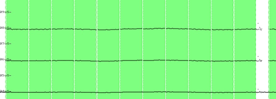
So, the green sections represent 11 sectors of data. It even detects them as AmigaDOS. Looks normal, data sits in the 4, 6 and 8uS as you'd expect. The white area is the 'gap' at the end that usually just fills the space to complete one revolution. Mostly this is ignored, and regardless, as I need to provide an accurate revolution of data to WinUAE this is fed in anyway. Copiers would usually just ignore this, but it looks strange, like there's some data there too.
Taking a closer look you can see this:
Well that's a little strange. So, ignoring the green areas which are data sectors, the right half of the image is just the 0xAA (01010101) sequence you often see, this is normal, but what's going on on the left hand side?
This must have something to do with it. My code already kept providing revolutions of data into WinUAE, this would allow it to bypass the 'weak bit' protection scheme as data mis-read would get re-presented differently each time. But what was going on here?
I decided to take a single revolution of data from the SCP file, and feed it into WinUAE, for just this track, and have it read the rest from the drive as before. The game booted! So clearly it didn't need multiple revolutions of data. So what was going on? If you look at the recording, this scatter of dots is different, so there is something going on.
There is clearly no way I can send that amount of craziness in 2M baud. I just don't have the bandwidth. But I do still had a few tricks.
This 'something else' case (the more than 3 0's in a row) that I was able to receive, which I was treating as an error maybe starting to mean something more useful.
I started reading up again about disks, and what they do if there's no flux data for a while. If you notice the timings, some of them are way up in 11-12uS. That's way out of range for MFM data.
So, drives have a circuit in them that automatically adjusts the amplification of head as its being read to compensate for disks recorded with different strengths of magnetic fields. After all, older disks still work, and their magnetic data will have started to decay.
Apparently, after about 3 zeros in a row it keeps trying to tune in, and eventually this amplification becomes so high that a bit might be detected that isn't even there. This is how the 'weak' bit stuff is suppose to work. When it actually detects a real bit, this gets massively overloaded and starts to revert back to its previous levels, and then the whole process starts again.
Looking at the data my code was reading, this special case was being tripped quite a lot, but how was I handling it? Incorrectly obviously. But I couldn't report sequences of 00001 or longer, I just don't have the bits. But what if I didn't have to. What if I only needed to know that we'd gone past the possibility of the 0001 sequence, but without detecting a '1', ie, confirming an '0000' sequence.
So I made some changes so when this was triggered it generated four zero bits, but the game still didn't boot. So I looked at the condition that triggered this. We waited in a loop, until we saw a bit, or the timer overflowed. The overflow being what may have triggered, or a bit way beyond the standards. This means that 00001 and 00000 would be detected as the same thing. But they're not.
I made this more strict. I changed the loop so it exited if the timer reached the 8uS boundary or hit a bit. Unless the bit was exactly on that boundary we would now know accurately we found a 0000, and any future '1' bits would be detected on the next loop. ie: we could detect 0000 and then 01, meaning we successfully detected 000001.
Did it work? no. I slept on this and came back to it in the morning.
A thought occurred to me. In between the checks for bits I perform other tasks, such as sending data to the PC or checking if the INDEX pin had signalled. What if a bit pulse arrived during this time, and the pulse was short enough that by the time we got back to checking for it, it had gone, and we missed it.
Is there a better way of watching for data? Well learning from how I now detect the index pulse, I started looking at the data sheet. The method I used there wouldn't work as the data wasn't coming in on a pin that could detect rising or falling edges. The ATMega328 does however allow you to setup an interrupt for pin state change for every pin.
I don't want an interrupt, but it must signal that one should be generated. Sure enough, if I do this:
PCMSK2 = bit(PCINT20);
PCICR = bit(PCIE2);
This would normally setup an interrupt when the state of the pin (4) changes. You can only detect changes though, not edges. Not massively a problem. If we know we're not in a pulse, then the change would be the pulse, and as long as we wait until the pulse is finished before resetting then all should be ok.
Our main 'detect pulses' loop now looks like this:
while ((!(PCIFR & bit(PCIF2)))&&(!(TIFR2 & bit(OCF2B)))) {}
Basically, wait in the loop until the pin changes or the timer reaches the upper 8uS threshold.
Then at the end I add the following:
while (!(PIN_READ_DATA_PORT & PIN_READ_DATA_MASK)) {};
PCIFR |= bit(PCIF2);
Bingo! The game booted! You cannot believe how happy I was! Whilst the above seemed like only a few days of work, this was evening after evening, after work for about a month to get this to happen.
This copy protection used two methods, firstly, valid sectors which everything would read correctly, then hiding some data in the sector gap but hidden in-between unformatted areas. This data would not normally be copied.
Now, I'm not saying this will bypass every copy protection, but these are the only ones I have to try, and they both work. If anyone has any others that don't work with this, well, then I guess we'll have to see if I can get a copy and try it.
For now though, I'm done. It's been a lot of hair-pulling fun trying to achieve this impossible goal, and I'm so pleased that I didn't give up. These little Atmel devices can do so much more than you expect if you take time to study the data sheet. They kind of remind me of the Amiga in their own way. They have lots of special options like timers, counters watchdogs etc available at the hardware level that you just need to enable, leaving the CPU to do other things. So much of the code I see around the Internet makes me sad. I see PWM being done manually when the hardware can do it. I see people wanting to count pulses externally, and end up in loops, and sometimes interrupts, when neither of these are required. Anyone that's interested in embedded programming, I strongly urge you to read the data sheet and programming guide! There's so much more to these little devices.
I decided to do some checking on the differences between the FTDI and CH340 USB to Serial converters. Short answer, they both work perfectly for small amounts of data (like a few bytes), but for streams/large amounts of data, the CH340 can't cope and the data starts to get corrupted. So, don't use any CH340 converters for this project.
Also, at the same time I tested the USB to Serial device on the Arduino UNO. Same problem. So, for this project, you MUST use the FTDI converter.
So, having never owned an Amiga with anything before Kickstart 2.04 I never really had the opportunity to test this. This was until I tried writing a few ADFs from the Internet to disk so I could try them. The disks were some old Demoscene sequences, and very good too, but they weren't compatible with Kickstart 2+. I found one of my old disks that had a copy of Relokick and booted back to Kickstart 1.3
Weirdly, the disks I had written wouldn't load at all. It was like the OS couldn't detect anything. After going back to the code and comparing the data of a disk that did work, and one that I had written I discovered something very interesting.
Back when I was originally working on the reader, I read about it being a bug in Kickstart 1.3 that some disks were encoded with 2AAAAAAA44894489 (starting with a 2, not an A). After a more detailed look this isn't a bug after all. The '2' had to be placed there or the MFM sequence would end up with two '1's in a row which isn't allowed.
I know that the trackdisk device in Kickstart 2 and above had been re-written so I assume they just ignore the 2AAAAAAA part all together and just looked for the sync word (4489). Upon fixing this and re-writing the disk it all worked perfectly.
I'd been very pleased with the disk access from WinUAE, and at this point it wasn't publicly available. I had however been releasing copies out to a few people for further testing.
One such tester was really into the Demoscene and had commented that some of these demos did some crazy things with disk access.
One specific demo he told me about was called Spaceballs - State of the Art
So I decided to download it, wrote it to a floppy disk, and tried it on my Amiga. Now this really is an interesting demo, from an engineering point of view. The moment the disk was inserted the demo started, like instantly, and while it was playing it was loading the next pieces in the background. The entire demo was timed so that the animations and effects lasted for long enough for the data to be read from the disk.
For fun, I tried it on WinUAE. Not so good. The disk just couldn't keep up. I wasn't surprised, lets face it, there is a lot going on to even make this work.
So inspired by this, I wondered if I could speed up the disk access without affecting the performance in WinUAE. I needed a baseline to measure.
My baseline, using the Captain Planet disk. I timed how long it took from the moment the WinUAE window appeared, to when the game music started playing, a mere 21 seconds:
Theres several factors affecting the slowness. The main ones are when the emulator switches to a track/disk side I start reading the data instantly. But it won't be available to the emulator for around 200ms absolute best case. The emulator then re-plays this data, taking a further 200ms. The problem is, the code needs to extract a full revolution of the disk so that WinUAE sees a complete track that perfectly loops.
I'd achieved this by noting where the INDEX pulse was on the drive, and then capturing all the data between that and when it occurs again. The index pulse isn't perfectly aligned, but it's close enough that we can do a rough compare to perfectly align the data.
So before we even start reading data to send to the emulator we have to wait for the first INDEX pulse. Worse case, thats 200ms. So for a single track, it could take upto 600ms before it's actually been processed by the Amiga OS, best case, around 400ms.
I wondered if there was a way I could do-away with this and capture a revolution without the index pulses. So I set about re-writing the code, as it was a little bit of a mess, and now having a grasp how it all works I could probably write it a little better.
My thought was, I knew the time it took for each bit-cell, so could I instead invent a virtual INDEX marker by timing approx 200ms of data and then patching up the seem.
Well, that didn't work very well. Turns out, and I should have realised that, not all drives spin at exactly 300rpm, so wouldn't be exactly 200ms.
So I decided to use the INDEX pulses to first time how long a rotation took, and then use that information to help better align a track. This worked, and after a little bit of tweaking I now had a slightly faster and improved loading. We'd gone from 21.23 seconds, down to 19.5 seconds, shaving off nearly 2 seconds!:
Not bad. After watching a few disks boot I had a fw other ideas. Firstly, whenever the emulator requests something of the drive, the code aborts reading whatever it is reading. Uncompleted tracks are discarded. So, if at the time of the abort request the track was at 90% or more complete and the code had no record of this before, then the abort was ignored so the track read could complete. This technically might slow it down by roughly 20ms, but its such a small edge case that is bound to speed up reading this track later on.
After measuring this, I couldn't really see any difference. So what else could I do? I noticed that the games I had seemed to be well optimised. Typically these disks would see to a track, read it, then switch to the other head (upper or lower) and then read that.
I decided that after extracting one revolution and presenting it to the emulator, whilst the OS was reading it I'd switch sides and read that too. This is dead time so might as well use it for something. I think this is called read-ahead caching, or at least that's what i'm calling this. For disks that aren't optimised this wouldn't make any difference, but lets try our benchmark.
Booted up, and oh, 16.14 seconds! So thats nearly 5 seconds faster than the first attempt, and 3.5 seconds quicker than the previous attempt:
So with these changes, for this game, I sped up access by around 24%. Thats great!. Don't mis-understand, we're not reading the disk any faster, just reading it more efficiently. Now what about that original Demoscene demo I was trying. Well, it runs a lot better, still can't keep up, but much better. For reference, on a real machine, Captain Planet takes just over 12 seconds, so theres still a lot of improvement that could be made.... if I could just figure out how...
One last thing, I decided to call all of this technology (for fun) RIT™ (its like JIT - Just in Time) which stands for Read in Time(ish)
I'm sure most of you discovered this project from the fantastic video that Neil at RMC - The Cave did in June 2021.
As a long-standing Patreon of his YouTube channel I figured it would be great if he was the one to officially break the news regarding WinUAE and I'd been communicating with Neil on and off for about a month before sending him anything. The first was the Nano he briefly showed in the video, and with him re-building the cave in a new location he hadn't been able to give any time to looking at it until I sent him the Slimline drive.
Working with Neil has been fantastic. We shared a quick call on Discord to talk him through it, then it was just a waiting game, although I had no idea what the video would be like until he released it.
Well, as you have seen, the video is great and Neil did a really good job of telling the story in just the right way. I don't think either of us expected the video to be viewed as many times as it did, and I thank everyone for their support. I am slowly working my way through the waiting list so please be patient. I didn't expect the response!
After several years of calling this some crazy long name about Arduino and disks, a popular name on discord arose... DrawBridge
Disk Reader And Writer BRIDGE (bridge between the drive and the computer)
I'd been doing some experiments and despite everyone being excited about heating the drive clicking, it was time to make no-click work. This was actually really simple because its triggered when the emulator tries to step to track -1. This isn't allowed. So all I had to do was capture this event (which was being ignored) and ask the drive to do the same. And it worked! That was easy...
So i'd been experimenting with disk writing within WinUAE. Some of the writing had been intermittent. Well, the writing was ok, but various applications were reporting errors.
The problem is, it takes about 200ms to collect the data from the emulator, then 200ms to write it to disk, then another 200ms to read it back, and then finally 200 ms for the emulator to read it back in. Problem is, once the emulator has submitted its 200ms of data it instantly was reading the data back to verify it. Bit I couldn't supply the data yet and so was just sending back my usual '1' (no data). Turns out most things timed out before the data became available. Not surprising really...
So how to get around this? Well, it occurred to be that copy protection probably doesn't care about disk writing, and whilst this solution would probably not work in every situation it may help here.
Typically when writing to the disk, the Amiga sets up a DMA transfer. This is obviously simulated in the emulator. You may have noticed the disk speed settings, well basically these mess with the DMA transfer speeds (usually by not simulating the actual transfer time).
I decided that I would grab the data from the DMA buffer the moment it started and write it to disk right away. So, that gets rid of the first and second 200ms delay! But I still had to read it back. Well, I figured if I then read the data back, and only when I had read a revolution of data I would then signal the Amiga that the DMA operation had completed.
Amazingly this worked! I tried disk copy with X-Copy. That worked. I actually tried copying from one real disk to another... Amazingly it worked! That was quite an easy one...
So while I was working on all this HD stuff, behind the scenes, the drive I had sent to Neil @ RMC had been on its own travels. It ended up in Mike Daillys (Game programmer, creator of Lemmings and Grand Theft Auto) hands and he used it to recover data from disks containing the original Lemmings level editors. How cool is this!
I really hadn't considered support for HD floppy disks when I started this project. Having never owned an Amiga with an HD floppy drive it never occurred to me. The comments in the video produced by RMC showed that this was much needed.
First issue though, how would I know if I'm reading and writing an Amiga HD floppy disk correctly if I don't own a drive to test it on. HD floppy drives for the Amiga are really hard to come-by for the Amiga. They were only included in some of the larger big-boxed Amigas, and you couldn't just use a PC HD floppy drive.
With an HD floppy disk, the data is encoded at twice the speed. Those 4us, 6us and 8us timings become 2us, 3us and 4us. Paula, the chip in the Amiga that was responsible for reading the MFM data from the drive, couldn't handle the faster data rate and so Commodore built specific floppy drives for the Amiga that when detecting an HD floppy disk, span the disk at half the speed (150rpm instead of the usual 300rpm). This allowed the data to be received the same speed for DD and HD floppy disks.
There are several projects around claiming that you can mod a normal Amiga floppy drive as the pads for the switches on the motherboard are present. Sadly this didn't work for either my A500+ or the A1200.
I had a long discussion regarding this on my Discord server. My original plan was to at least get someone to send me an HD floppy disk written from a real Amiga, but even that proved difficult.
Then, two members on my Discord server came to the rescue. We'd all heard that some Sony Drives had been modded to spin at this slower speed, but details were never present. Hany (Hany Tahvilzade) and Siliconix (Siamak Habibzade) sent me a modded Sony drive. The solution came in two, a special interface board that plugged into the drive's connector, and some internal re-wiring going off to a custom board. I have no idea how it works, and it would be unfair for me to try. I am very thankful for these two for sending this. I have since printed a 3D case for it and added a cable so it can properly act as an external Amiga HD floppy drive.
OK, so I had a drive. First question, how does the Amiga actually know when an HD disk is present? The Amiga floppy drive doesn't have an "its an HD disk" pin. So how does it know? Seems like magic.
Well, starting with Kickstart 2.04, HD floppy disks had been supported, and the way they are detected is actually quite simple. Reading this page (does not mention HD) and this thread:
Now that I had access to HD Amiga disks, I turned to reading and writing them in DrawBridge. I first attempted with writing, seeing as the writing code for DD disks was now all based on hardware timers I knew this could be done accurately with little effort.
I set about writing a version of the write function for HD. The only difference being that now I was sending twice the amount of data as before. This meant there was no longer enough bandwidth to send the extra information for write pre-compensation. Never mind.
I was sent a link to aminet - disk/misc/Empty_ADF_files.lha which contained six ADF files, three in DD and three in HD.
To write one of these HD ADF files I first needed to understand the difference. The only difference being that there was twice the number of sectors per track. I set about modifying the code to understand and support this, fairly trivial.
Finally, I used a logic analyser to check the pulses I was creating were indeed at 2us, 3us and 4us. This is a PC drive, we can't spin it at 150rpm, we have to work at the full 300rpm.
I wrote a disk, tried it in the Amiga, and amazingly it worked! Although I couldn't write with verify, because I hadn't written the HD read code yet.
Reading the data seemed like it should be fairly straight forward too. Once again, there wasn't enough bandwidth available to send raw flux timing data, but I could send my detected MFM bit-stream back. This would never work for copy protected HD disks, but I doubted that any copy protected games were ever distributed on HD media.
My first attempt utterly failed. Partly due to the fact that all of the code that checked for valid Amiga sectors was expecting 11, not 22. Once that was upgraded I tried again, but still was less than successful, in fact I couldn't even read a single sector back.
I started to simplify the code Arduino side, removing parts that, whilst useful, were not 100% essential. I looked at the main loop, that was waiting for a pulse from the disk:
while ((!(PCIFR & bit(PCIF2)))&&(!(TIFR2 & bit(OCF2B)))) {}
It worked fine for DD disks, so why not HD disks? Well, it turned out I just didn't have the clock resolution for this. Let me explain:
To have gotten to 2uSec, there were a maximum of 32 clock ticks, assuming instructions were 1 tick (some aren't), that was a theoretical maximum of 32 clock-ticks/cycles I could waste before checking the counter value.
Ignoring, the 3us, and 4us, there was an issue here. If I take the above code, and disassemble it, we got (and i've commented):
  sbic	0x1b, 2	    (1/2) Skip next instruction if bit 2 is CLEAR in I/O register 0x1B (PCIFR) is not set
  rjmp	.+4         (2) Go back to the line above
  sbis	0x17, 2	    (1/2) Skip next instruction if bit 2 is SET in I/O register 0x17 (TIFR2) is not set
  rjmp	.-8         (2) Go back to the first line
This basically stayed within these four instructions until PCIFR gets set (a pulse arrived) or the timer 2 overflowed (ie: when no disk was present). What's wrong with that? Well, it wasn't reliable. I added some code to toggle another pin when a pulse was detected, and the result jittered around, a lot.
The numbers in brackets above were how many clock cycles each instruction would take to operate. So if we ran the code, and stepped through line by line, if a pulse arrived when we weren't at the first line, it could have taken up to a further 5 clock cycles to actually be detected and captured.
This was less than ideal. At 16Mhz, the Arduino clock speed, there were literally a maximum of 16 clock ticks between detecting a 2us, 3us or 4us pulse. Something had to give.
I removed the second test. Yes, that meant that the code would get stuck if you removed the disk, but it was better than nothing.
After looking at the data coming in, I was starting to see something resembling data, but it wasn't perfect. The jitter was reduced to about +/- 3 clock cycles now though.
Because of the jitter, I wondered if I could resort back to my original ideas from a few years ago and have the pulse detection being interrupt driven.
Due to a design decision that at the time I was unaware of, the pin I was using for read, could only be serviced by the shared pin interrupt. Not a problem, as there would only be one pin we would want to trigger on. The issue being that you couldn't choose if it was detected on rising or falling edge, it was literally a pin changed state trigger.
No problem, I could account for this. But I already knew the overhead of a standard interrupt was way too high. Could I code a faster one?
I implemented a naked interrupt service routine (ISR), pushing and popping just the registers I changed. I included the code to toggle a pin on the Arduino when a pulse was detected so I could check it was reacting properly.
There was still jitter. Less jitter, but it was still there, and still the +/- 3 clock cycles. Strange! So I started re-reading the datasheet for the ATMega328. Before an ISR is actually ran/serviced, the current instruction must complete. The main loop at this point was monitoring for the timer overflowing again, seeing as I could be able to do this. The jitter now was coming from which instruction the CPU was actually executing at the time the pulse occurred.
With the extra overhead, and the fact that it did not improve the results I ditched the interrupt handler.
Now that I was more aware of how long instructions were taking, I started looking at if the code was actually able to run fast enough to start with, worse case, with the loops, and what I could do to speed things up.
I disassembled the code again to see what was going on. I created a flow chart showing the possible instructions for capturing each bit-cell, and calculated the number of clock ticks required by each route, for 2us, 3us and 4us.
The current implementation was based on several if statements. Whilst this was very obvious what it was doing, looking at the disassembled code was less than ideal. The compiler was trying to optimise some things in a way that I'd rather it hadn't, and as such there were extra RJMP (effectively goto) in the code than needed.
I came up with a plan to change the way I processed this. Luckily, the 2us, 3us and 4us were exactly divisible by 16, and fitted perfectly with the frequency of the Arduino.
The basic calculation I needed, for which type of sequence (2us=01, 3us=001, and 4us=0001) was actually straight forward. I took the timer value, offset it so the bit-cell fell in the middle, and divided it by 16.
It's interesting how the compiler optimised this. Internally it didn't do a divide 16, it called swap which swaps the lower and upper nibbles. It then anded with 0x0F to just keep the now-lower nibble.
The corresponding numbers were now, 0 & 1 = 01, 2=001 and 3=0001. For most branches this worked out slightly quicker. But it still didn't fix anything.
So what else? I started looking at the other timers. Ignoring Timer 1, being a 16-bit timer, I looked at timer 0. I discovered something strange. Timer 0 could also be accessed using the asm IN and OUT instructions, rather than LDS and STD. LDS and STD require 2 clock cycles per operation each, whereas IN and OUT only require 1 each. There was two clock cycles I could save instantly.
I made this change, and wow, I managed to read the disk back perfectly that I had written previously. I knew that disk read properly in a real Amiga, so I therefore knew I could read Amiga disks now properly. Why did this help? Well, I began to realise, by removing 2 clock cycles, it effectively made the code faster, but more importantly, TIMING_OVERHEAD, which was -6, effectively compensated incorrectly. It was now -2 less, giving -8. 8 being the magic number, because if we were at one bit-cell, the threshold between 2us and 3us is +/- 8 clock ticks. This probably meant it was still wrong for DD disks, but as they were working I left it was it was.
So, now lets try a few disks written on the Amiga...
I booted up my A1200, after attaching the HD drive, formatted a disk, and began filling it with anything from Workbench I could find. A few minutes later I had filled the disk.
I then inserted the disk into my drive, and started trying to read it. Strange, I was getting partial success. It was reading some sectors perfectly, but others not. This really didn't make much sense. I knew I could read a disk, as I had above, so what was wrong with this one?
I decided to dump the disk using Greaseweazle and have a look at it under HxCFloppyEmulator's Track Analyser.

The blue, green and yellow areas represent the three bit-cell groups. The red line is the ideal position where these timings should be detected. The grid lines represent the 16 timer values between eah window. The darker blue, green and yellow represent areas that are very close to the boundary of another window, which could be affected by our jitter.
That was one wavy set of lines! The technical term I believe was flutter. This does happen with all rotating media (including LPs), although this was quite extreme. Notice that some of the bit-cells actually fall into the darker regions. No wonder I couldn't read it. This could be the drive or the disk, or both.
I wondered why I was able to read mine. Well, I decided to do the same with one of my disks I had written:
There was less data there, that was to be expected, it was blank formatted disk, but the flutter was a lot less! So how did the Amiga manage to read both disks?
Well, I imagine that it would be a combination of two factors. Firstly, the disk was read back on the same drive, and as the flutter would match the recording, to the Amiga it would appear flatter. Secondly, Paula (the chip that did the reading) had a basic PLL implemented inside. This would dynamically adjust the clock speed, thus moving these windows dynamically as the disk was read, effectively riding these waves.
Could I implement something like this? I would think so, but there wasn't going to me much room for movement, it would only be +/- a few timer values based on our speed.
A second consideration was the speed of correction. If it was too slow it would be pointless, too fast and it would corrupt the data just as much. If I was to implement this on the DD code I would need to be careful as this could affect copy protection, but with HD, I didn't care.
I knew now, that the above is an extreme case, and any of the PC HD disks I had looked perfect after viewing them in HxCFloppyEmulator Track Viewer. That meant that the generous donated drive was probably not the best example of running at 150rpm. I suspected slowing this down probably made motor weaker and thus more flutter. I wondered if the original Commodore drives displayed this attribute too, but without an official one I had no way to know.
I made the assumption, that for most disks, the solution so far would probably be acceptable, great, so I had a working HD reader! But I couldn't let this drop. I wanted to make this work better.
To calculate and adjust the timer used, to simulate the effects of a PLL, I would need to record over time, how much the 2us, 3us and 4us differed/drifted from the centre point, then compensate by that drift amount.
Sounded simple enough, so I set about calculating that drift. The drift per sample was easily obtained using the following:
7-(counter & 0x0F)This would work, because the divide by 16 removed this lower nibble, and this lower nibble had the error value in it we needed. So, over four bit-cell reads I added this error value together. This error value should be +/-7, so with jitter, over time, would cancel it's self out. If it was running faster or slower this number would drift over time.
When this number drifted too far I would reset the total counter, and then increase or decrease a compensation value accordingly.
Well, that was the theory. I started to measure this, and output the result, so I could monitor it. The result was unstable, but I wasn't sure why. I started down the rabbit hole of maybe the added code had slowed it down too much, so I re-coded this entire block in assembly language. After I got that working it still didn't make any difference, if anything, it made matters worse. (You can test this yourself by enabling the ENABLE_PLL define round line 1766 ish.) Tired and defeated, I decided that this was as far as DrawBridge could go. The jitter caused by the timer reading was the limiting factor. The positive being that most HD disks probably would work OK.
You know when you have an itch that you just can't scratch? Well, a week on, and I was still not happy about this. I knew there was nothing I could do to speed up the code, but had I missed something? The irony of my own comments hit me. At some point I had commented about how these devices had sometimes been used poorly to do something that the hardware could already do. I studied the data sheet again, actually spent several hours reading it. Then I spotted it. Something I had never spotted before. Timer 1, the 16-bit timer. I'd overlooked this because I didn't need a 16-bit counter, but unlike the other two, this one had a special feature.
Timer 1, could be configured in input capture mode. What this did was each time a pulse was detected (you could choose rising or falling edge) it would copy the current timer value into a special register, set a flag and trigger an interrupt. The best part about all of this is it would all happened in hardware without any loops, automatically. So this would mean there would be no jitter, and it didn't matter what the code was currently doing. Sounded great, but now I had a new problem. The pin used to trigger the input capture was Pin 8. We had the Read Data pin as pin 4. Pin 8 we were currently using to detect when the drive head was on track 0. This was a design decision I made about four years ago when I was starting out with Arduino. The choice was purely based on aesthetics for drawing the circuit diagram. The only way this configuration was ever going to work would be to change the pin configuration for DrawBridge...
I decided on the name for this new configuration as DrawBridge Plus, a nod to my first Amiga, the A500+. At first I was concerned about the different design, but I soon came to realise that 99% of people don't want HD support, and the remaining 1% may not need the extra accuracy anyway. That being said, I decided to continue anyway.
All anyone needed to do to upgrade to this version would be to swap Pin 4 and Pin 8, and then use my software tools to program the EEPROM settings value to signal this swap. I could make that really easy for everyone to do.
I slowly worked my way through the code producing a second version of every piece of code that read data, for the new pin configuration. The only difference really was that I would be waiting for a different register to be set and then calculating the difference in the captured time from the previous captured time. Also, the value of TIMING_OVERHEAD would become irrelevant as there would no longer be any overhead.
This was easy, I felt confident. Now back to the HD code. I started with without the PLL code, I was never 100% sure it was working correctly anyway, and besides, this new method may prove to be enough. Sadly that wasn't the case. It still wouldn't capture all the sectors on the disk properly. Again, I was concerned the code may not have been running fast enough, so I wrote an ASM version. That made no difference, but was interesting learning how.
Back to the PLL. This time however, when I switched it on, the disk read perfectly! Yes, the crazy one! Because there was no jitter, the code was able to follow the flutter aka speed changes during the disk rotation and compensate for it.
This reminded me of one of the copy protection schemes, which placed flux transitions on the borders between the MFM sequences, and because of the PLL, would sometimes be tricked to be in one or the other side. Copying the disk would fix this pattern.
I decided to add a PLL to the DD code too. I decided anyone should be able to switch this back off in the same way as the DrawBridge Plus mode could be switched. It may help, but incase it caused a problem it could be disabled.
I also thought that if you were just using the disks in Workbench for example, then copy protection also didn't matter. WinUAE has a disk speed mode, which also includes a turbo mode. Essentially these modes fool the operating system that a DMA transfer occurred much faster than it should have.
I wondered what would happen if I could make this an option. Well, I couldn't figure out how to make Turbo work, but I did discover I could just tell WinUAE the data arrived much faster. I had one disk (my modified Workbench disk), that took exactly 29 seconds to boot, so this was to be used as my test disk.
The result, the disk now booted in 25 seconds. Not bad, time to test the Spaceballs demo again...
So, Spaceballs, a good benchmark for this was when the original music stopped playing, which track was trying to read. In 'Fast' mode, this was always track 18. Ok, in the new 'Turbo' mode... we got to track 23! so it is much faster... (Real hardware would get to 28/29, the demo shouldn't stop!)!
Whilst looking at this I discovered a weird race-condition, and after patching it the demo now ran properly all of the time!
I needed to manually detect if the disk inserted was a DD or HD disk. Now that was fairly easy to do, I'd spin the motor up, started capturing data, and count how many samples were on less than 2us/3us or greater then 5us. Based on which had the larger count I should be able to detect the density. After some experimentation this worked most of the time. The only time it didn't work was with an unformatted disk. As PC drives couldn't detect DD vs HD, this probably explained why when you purchased blank PC disks, they usually came formatted.
My algorithm for density selection was, if the HD sense pin was low, then assume it was a DD disk, else run my test.
Based on my previous discovery, the Amiga uses this special drive ID sequence to identify the type of media inserted. This appeared to be triggered after a disk-change signal event. The problem was, by the time this event had been generated by the drive, I already needed to know what type of medium it was. WinUAE would manage the signals for me, but I needed to magically detect the disk type first.
So I set about modifying the bridge code, and when I detected a disk change event, before I let WinUAE know about itI would do a density test, just a momentary spin of the disk. After some modifications this worked great. Inserting a DD disk and trying to format said 880k, and switching it out for a HD disk came to 1760k! Perfect. And after a few modifications for the extra data requirements I could now read the disks from Workbench too.
Based on the above speed improvements I set HD disks to always run in this Turbo mode. They were real slow on original hardware, at least this way they'd be faster...
The main discussion points was the easiest way for me to continue updating support without having to have WinUAE recompiled. We decided that I would produce an 'API'. Essentially I would compile all of the Floppy Bridge code into a DLL, which WinUAE would read and use if it was present. Most of the changes would be in the DLL, and now that I had HD support, right now there probably wouldn't be any further changes.
There were also new options, and the way it was configured was starting to get messy. Toni wanted to work on his own GUI for this interface and I was happy with this.
This evolved a few times, and we reached a stable solution. I provide access to configuration profiles, and WinUAE calls a command in my API DLLs to show the configuration dialogs. Much easier.
I had another look at the datasheet for the ATMega328. Before I had the idea of using the timer as a one-shot to make the timings accurate. Seemed ok, but I wondered if there was a way so the timing stayed accurate.
Turned out there was, and it was actually quite simple. In FAST PWM mode, which is what I was using, the timer would count up to a number, and then reset back to 0.
I found that if I calculated that to be the total pulse length, and then updated it each time the pulse had finished, the timing stayed perfect. The reason was because the timer value was never changed in the code, only by the CPU, so no ticks were lost or had to be accounted for.
To make this work I also removed the use of the 256 byte serial buffer. It was actually using too much time doing what it was doing anyway. So, now I had DD and HD jitter free writing!
The other feature I wanted to implement was a little more difficult. I wanted to allow my 'Fast' (Turbo) mode to work in as many places as possible. I knew based on how some copy protection schemes worked that if I was just to switch this on all the time then some disks would not boot at all.
I decided that I could analyse the data for a track just after it has been read, and then work out the average 'speed' for that data. Then I could look at the track again, and see how much of the data differed from this average by a specific threshold. If that total reached a large enough number I would disable the 'Turbo' option.
Well, this was interesting, I imagine this wouldn't work with all disks, but my Lemmings disk now booted faster in WinUAE than on a real Amiga by about 5 seconds!
I've been asked several times why I chose to add Greaseweazle support, a competing product, to this solution. I wasn't paid anything to do this. I wanted to make the WinUAE solution available to as many people as possible. It is an open source solution, so available to everyone anyway.
The first time Keir (created Greaseweazle) knew about it was when I approached him with an early beta. People had been asking for this solution for a long time, but no one had taken up the gauntlet. I had a little concern he wouldn't respond as its kind of a competing product (although DrawBridge was first, and is in no way a competing product!), but he was very pleased, and allowed me to announce it when I felt I was ready. Between this first version I sent him, and the final release, I worked with Keir to get a few extra commands added to the Greaseweazle firmware (such as Disk Change support, and being able to read the Write Protect status when required) which he happily added. For those who don't know, he also makes the Amiga Test Kit, a useful tool for diagnosing faults with your Amiga.
I'm still working with Jim Drew to add support for the SuperCard Pro. Jim has been in the disk scene for a long long long time and is extremely knowledgeable about disks, copy protection and data preservation. He is also an active member of my discord server regarding copy protection etc. Jim sent me a SuperCard Pro board to help development, for which I am very grateful. This board was not only useful for working on adding support, but also very useful for helping develop support for HD Amiga Floppy Disks too.
My aim is to try to release a video every one to two weeks talking about retro, electronics, Arduino, programming etc. We'll see how that goes. You can check it out at https://www.youtube.com/c/RobSmithDev. Be sure to subscribe!
The problem I'd had was there just wasn't enough bandwidth in a 2MBaud rate serial connection to write data at a 25ns resolution, but now I realised I didn't need it. I started looking at what realistically I did need.
So first I set a few rules:
I created a spreadsheet that allowed me to play with numbers until I found a combination that would work and fit into the baud rate. The next issue though, is that it was perfectly possible to have a pause between pulses being very very large. I decided I could overcome this by having a special code that I could send that meant 'just keep going for a specific number of nano seconds without writing'.
I settled on using a 5-bit number to store the flux times, and with 5-bits, I was able to pack 8 flux timings into 5 bytes!
The spreadsheet allowed me to adjust some constants for the best and most flexible options. I decided that the minimum flux time that could be written was 2750ns. This would be encoded as a 0. Then Every time after that was 125ns more than the last.
This would continue upto 29. I reserved 30, which translated as 'pause for 3250ns'. Per 5 bytes (8 flux times), the total must be at least 260,000ns or we could potentially run out of data sending it quickly enough.
This worked out as follows:
| Time (ns) | Value | Arduino Time |
|---|---|---|
| 2750 | 0 | 44 |
| 2875 | 1 | 46 |
| 3000 | 2 | 48 |
| 3125 | 3 | 50 |
| 3250 | 4 | 52 |
| 3375 | 5 | 54 |
| 3500 | 6 | 56 |
| 3625 | 7 | 58 |
| 3750 | 8 | 60 |
| 3875 | 9 | 62 |
| 4000 | 10 | 64 |
| 4125 | 11 | 66 |
| 4250 | 12 | 68 |
| 4375 | 13 | 70 |
| 4500 | 14 | 72 |
| 4625 | 15 | 74 |
| 4750 | 16 | 76 |
| 4875 | 17 | 78 |
| 5000 | 18 | 80 |
| 5125 | 19 | 82 |
| 5250 | 20 | 84 |
| 5375 | 21 | 86 |
| 5500 | 22 | 88 |
| 5625 | 23 | 90 |
| 5750 | 24 | 92 |
| 5875 | 25 | 94 |
| 6000 | 26 | 96 |
| 6125 | 27 | 98 |
| 6250 | 28 | 100 |
| 6375 | 29 | 102 |
These were encoded into the 5 bytes like this:
| Bit Number | |||||||
|---|---|---|---|---|---|---|---|
| 7 | 6 | 5 | 4 | 3 | 2 | 1 | 0 |
| D4 | C4 | B4 | A4 | A3 | A2 | A1 | A0 |
| C3 | C2 | C1 | C0 | B3 | B2 | B1 | B0 |
| E3 | E2 | E1 | E0 | D3 | D2 | D1 | D0 |
| E4 | H4 | G4 | F4 | F3 | F2 | F1 | F0 |
| H3 | H2 | H1 | H0 | G3 | G2 | G1 | G0 |
To my surprise, this worked perfectly. I decided to just send one of the rotations from an SCP file, and there we had it. SCP files written to disk. This was something a few months before I never thought would be possible. Even I can be wrong!
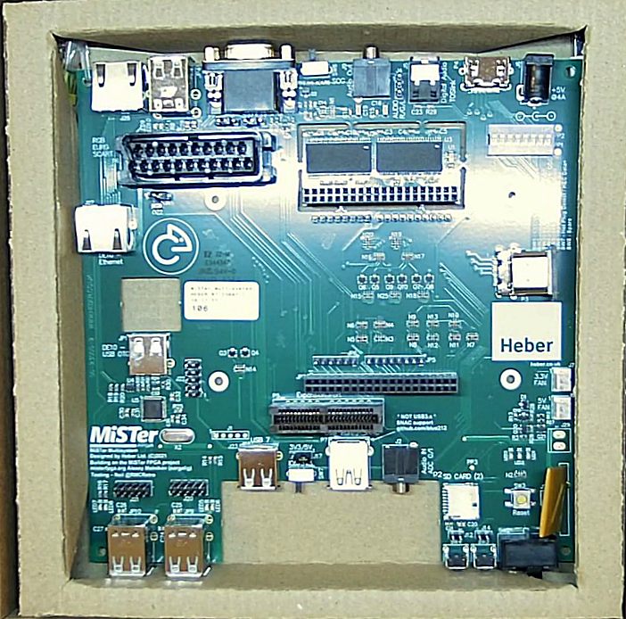
It's the main board for the MiSTer Multisystem. A single board for using the MiSTer setup. I was lucky enough to get one of the first 500. No special favours, I just got there quick!
See for more details of the progress with this project.
I've never been so busy to be honest. From building up PCBs to fulfill the waiting list, to adding new features. Now that I have my own YouTube channel, I'm even busier!
The FloppyBridge plugin for WinUAE is also supported in Amiberry too so you can use this on your Raspberry PI or Mac!
Keep an eye on my YouTube channel for updates!
If you enjoyed reading this and want to thank me, consider becoming a Patreon or making a donation. It's all free so it's entirely optional