Build One!
Building your own DrawBridge Plus (
what's Plus?) isn't difficult as most of it is just wiring. This can be done on a breadboard, breakout board, with DUPONT wires, or soldered together, and if you get stuck, ask for help on my
Discord Server or check out
troubleshooting.
Join the Waiting List for purchase of a ready-built solution! or Build your own NANO based USB slimline floppy drive - See instructions
NEW: 3D Print designs for an alternative case for Slimline Floppy Drives. These have enough space to fit an Arduino Pro Mini or Nano as well as my PCBs. Available now on Thingiverse
Which version do you want to make?
Older German Guide by Mingo. | Video tutorial, not made by me
There is no difference in performance, the choice you make should be based on your skill level (or if you like a challenge - see the Nano!):
 Requires an FTDI USB to Serial Adapter Board (DO NOT USE THE CH340 BOARDS)
 No Soldering solution available
 Requires a soldering iron
 Requires good soldering skills
 (or at least not your first attempt!)
Upgrading your original DrawBridge (Arduino reader/writer) board (WinUAE)
If you already have a board and want to upgrade it to get the best possible experience within WinUAE then you need to make the following modifications. These changes allow the Arduino to detect if a disk is inserted or not, and allows it to control th drive without spinning up the motor. Without these changes, the Arduino code will spin up the drive at regular intervals to perform a check manually:
- Pin 34 on the floppy drive connector (Disk Change) must be connected to Pin 10 on the Arduino
- Pin 12 on the floppy drive connector (Select Disk B) must be disconnected from Pin 5 on the Arduino and connected to Pin 11 on the Arduino.
Note you must leave the connection between Arduino Pin 5 and Floppy Connector Pin 16 in place
- On the Arduino, connect Pin 12 to GND (0v) - this lets the firmware know you have made this modification. Using the ISP to program?
- Version 1.8 software must be uploaded
Upgrading DrawBridge to DrawBridge Plus!
DrawBridge Plus is a simple change, and software update that improves the accuracy of reading. This is not required for reading DD disks or most HD disks, however, with really poorly written HD disks it can help.
All you need to to is simply swap what is connected on Arduino Pin 4, with whats on Arduino Pin 8. (The 1K resistor should now be connected to Arduino Pin 8 too)
Flash the new firmware, V1.9.17 onwards, then use the diagnostics option to check it. Also use the DrawBridge Config button in the Windows app to set the 'Drawbridge Plus' mode (it won't work if you don't!)
If the above doesn't make sense, check out the new diagrams for each board.
PC 34-Pin IDC Cable Guide
Assuming you have cut the cable and the piece you are using does not have the twist in it, then locate the wire with the red stripe. This is Pin 1, and they continue in sequence, every other wire being a GND. You usually don't need to connect up the GND wires as they are all connected together anyway inside the drive.
If you are having trouble with the floppy drive cable then the following diagram might help (the red line is the red marking on the cable. Make sure you aren't using the part of the cable with a twist in it):

Programming the Arduino
Once you have all of the wiring complete, you now need to upload the program onto the Arduino. It's easy.
- Download and install the Arduino IDE.
- Connect the Arduino to the computer as follows:
- Arduino UNO: Use the on-board USB connector
- Arduino Pro Mini: Use the break-out board
- Arduino Nano: Use the on-board USB connector (if it fails, try the old bootloader option)
- Official DrawBridge and DrawBridge Plus Boards: Connect the board as normal. Pretend it is an Arduino Nano, and use the New Bootloader option.
- After a few moments the drive should be detected and be ready to use. If not you may need to install additional drivers. You may need to restart your computer, although sometimes just disconnecting and reconnecting a few times achieves the same result.
- From the Arduino IDE select the type of board from the Tools->Board menu:
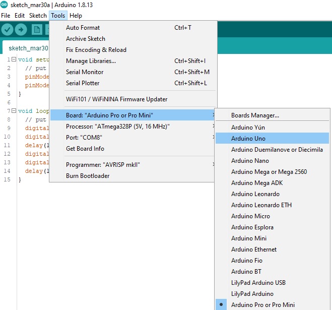
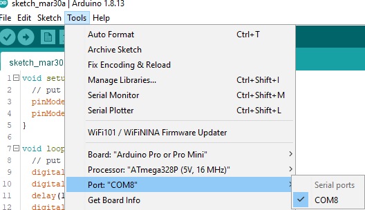
- Next, choose the COM port the device is connected on from the Tools->Port menu:
- To test the board, I recommend first programming it with the BLINK example. Goto File->Examples->Basic->Blink - if you're feeling brave, change the numbers in the delay() functions to 100, that'll blink a lot faster.
- Now upload the blink program by going to Sketch->Upload. Some LEDs should flash for a while on the board, and then afterwards, you should see one of the LEDs turning on for one second, then turning off for one second, repeating.
- Once you're happy thats working, download the Arduino sketch from either GitHub or from this website. and load the file into the IDE.
- Now program it in the same way as before, by going to Sketch->Upload.
DrawBridge PLUS Mode
By default, the Arduino sketch assumes the board is a DrawBridge Classic design. To change this, load the Windows Application, and either run Diagnostics, or use the DrawBridge Config button.
Diagnostics
So, you've connected everything up and you've programmed your Arduino. I've included a diagnostics option to help you figure out if everything is working correctly. You will need a floppy disk that you don't care about, and the
application available on the downloads page. This will run through a series of tests which should help you troubleshoot. Either that, or just go for it and try it out!
More Help and Other Guides
If you get stuck, there are loads of good examples showing you how to set up and get started with Arduino, for example: