<< Back |
How to build your own Arduino Uno DrawBridge (Amiga Disk Reader/Writer)
Hardware Required
Note: Links to hardware on Amazon are Affiliate links.
These are not recommendations, these are examples. Please check they are suitable for the task.
Optional Hardware
- 1 x 5V power supply (See below)
- 1 x 12V power supply (Probably not needed, I haven't seen a drive need one yet)
- 1 x FFC Breakout board (for 26-pin drives) if you don't plan on soldering directly to the drive like I have
- 1 x Arduino Uno Screw Shield or Terminal Shield - Solder Free Solution! or a soldering iron or breadboard shield
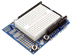
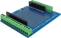
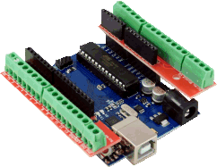
Example of an Arduino Uno Prototype Shield & Terminal Shields/Screw Shields
5V Power Supply
Depending on how much power the drive you have uses, and how much power your USB ports can provide you may not need this.
- WARNING: The UNO has a MOSFET between the USB and 5V pin. This can drop the power below what some drives actually require! You can try finding and bypassing it, or...
- If the USB port does not provide enough power (usually causes the Arduino or drive to keep resetting) then don't connect the dotted red line, and connect the drive to an external 5V supply.
Wiring Diagram
Connect the cable to the Arduino as shown in the diagram below. You can either solder these or connect them using some kind of breakout board (above)

Connections/Pinout
Depending on what type of drive you want to connect to I have listed the wiring below. Please note that there are different variants of the slimline 26-pin drives and they are not always easy to tell apart. The best way would be to get a multimeter and test for connections between the GND lines, or the 5V lines as with the wrong variant these won't be connected together. Also note, these are the two I have discovered, there may be more. To be honest, it kinda looks like
someone put the FFC connector in backwards to me
This is the wiring for DrawBridge PLUS! - You will need to run diagnostics/use the
DrawBridge Config option for the Windows App to set this. Its more accurate than original DrawBridge.
DrawBridge PLUS Wiring
| Arduino | PC IDC | Slimline 26-pin FFC | PIN | PIN |
|---|
| PIN | 34-Pin | Variant A | Variant B | Name | Code |
|---|
| 0 | | | | TX on adapter (see below) |
| 1 | | | | RX on adapter (see below) |
| 2 | 8 | 2 | 25 | Index | /INDEX |
| 3 | 22 | 16 | 11 | Write Data | /WDATA |
| 4 | 26 | 20 | 7 | Track 0 | /TRK00 |
| 5 | 16 | 10 | 17 | Motor Enable B | /MOTEB |
| 6 | 18 | 12 | 15 | Direction | /DIR |
| 7 | 20 | 14 | 13 | Step | /STEP |
| 8 | 30 | 24 | 3 | Read Data * | /RDATA |
| 9 | 32 | 26 | 1 | Head Select | /SIDE1 |
| 10 | 34 | 6 | 21 | Disk Change | /DSKCHG |
| 11 | 12 | 4 | 23 | Drive Select B | /DRVSB |
| 12 | | | | Connect to GND | Enables DiskChange
Support for WinUAE
Using ISP? |
| A0 | 24 | 18 | 9 | Write Gate | /WGATE |
| A1 | 28 | 22 | 5 | Write Protect | /WPT |
| A2 | | | |
CTS on adapter (see below) |
| A3 | 2 | 9 | 18 | Density Select | /REDWC |
| 5V** | | 1,3,5 | 22,24,26 | 5V |
| GND | odd
numbered
pins | 15,17,23,25 | 2,4,6,8,
10,12,14,20 | GND |
* 1k pull-up resistor required
** If drive is powered by separate source do not connect to Arduino
FTDI Adapter Connection
The
onboard USB to Serial interface
isn't able to keep up with the throughput of data this project requires. Also, to write disks, the Arduino needs access to the CTS pin on the RS232 interface to control the flow of data (This pin also isn't available either). This means we
have to use a separate board as follows:
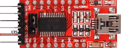
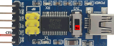
Typical FTDI Adapters. Note the pin order, from top to bottom
DTR, RX, TX, VCC, CTS, GND
Also note the voltage switch. We're using 5V Arduino so set it to 5V
Use the Arduino's normal USB port for programming, and then this connection to read/write disks. You need to connect this as above in the pinout.
Note: It is possible to power the Arduino UNO using the 5V on the FTDI adapter board
Tip: While the FTDI board is connected, you may not be able to program the Arduino.
PC 34-Pin IDC Cable Guide
Assuming you have cut the cable and the piece you are using does not have the twist in it, then locate the wire with the red stripe. This is Pin 1, and they continue in sequence, every other wire being a GND. You usually don't need to connect up the GND wires as they are all connected together anyway inside the drive.
If you are having trouble with the floppy drive cable then the following diagram might help (the red line is the red marking on the cable. Make sure you aren't using the part of the cable with a twist in it):

Programming the Arduino
Once you have all of the wiring complete, you now need to upload the program onto the Arduino. It's easy.
- Download and install the Arduino IDE.
- Connect the Arduino to the computer as follows:
- Arduino UNO: Use the on-board USB connector
- Arduino Pro Mini: Use the break-out board
- Arduino Nano: Use the on-board USB connector (if it fails, try the old bootloader option)
- Official DrawBridge and DrawBridge Plus Boards: Connect the board as normal. Pretend it is an Arduino Nano, and use the New Bootloader option.
- After a few moments the drive should be detected and be ready to use. If not you may need to install additional drivers. You may need to restart your computer, although sometimes just disconnecting and reconnecting a few times achieves the same result.
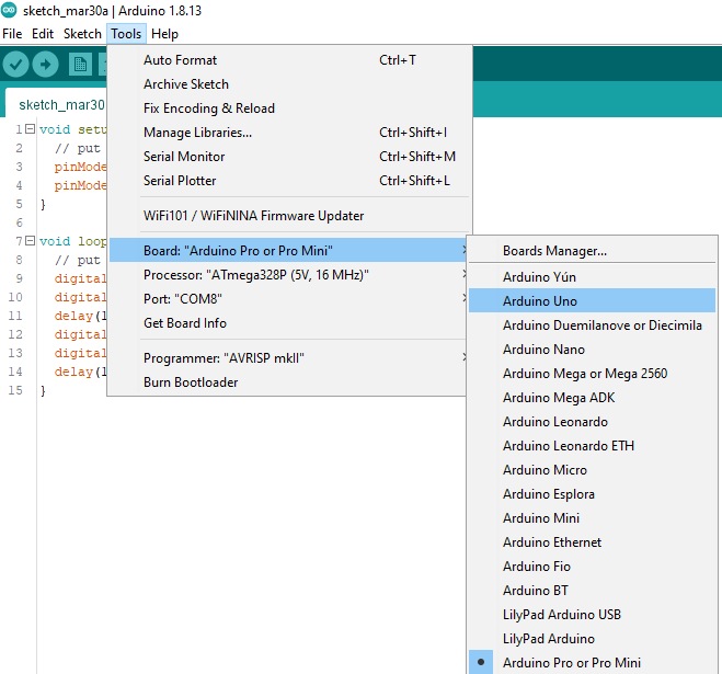
- From the Arduino IDE select the type of board from the Tools->Board menu:
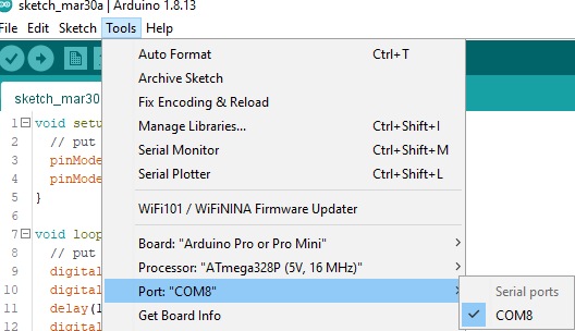
- Next, choose the COM port the device is connected on from the Tools->Port menu:
- To test the board, I recommend first programming it with the BLINK example. Goto File->Examples->Basic->Blink - if you're feeling brave, change the numbers in the delay() functions to 100, that'll blink a lot faster.
- Now upload the blink program by going to Sketch->Upload. Some LEDs should flash for a while on the board, and then afterwards, you should see one of the LEDs turning on for one second, then turning off for one second, repeating.
- Once you're happy thats working, download the Arduino sketch from either GitHub or from this website. and load the file into the IDE.
- Now program it in the same way as before, by going to Sketch->Upload.
DrawBridge PLUS Mode
By default, the Arduino sketch assumes the board is a DrawBridge Classic design. To change this, load the Windows Application, and either run Diagnostics, or use the DrawBridge Config button.
Diagnostics
So, you've connected everything up and you've programmed your Arduino. I've included a diagnostics option to help you figure out if everything is working correctly. You will need a floppy disk that you don't care about, and the
application available on the downloads page. This will run through a series of tests which should help you troubleshoot. Either that, or just go for it and try it out!
More Help and Other Guides
If you get stuck, there are loads of good examples showing you how to set up and get started with Arduino, for example: