New: Join the Waiting List to purchase a professionally made board ready to drop into one of these drives!.
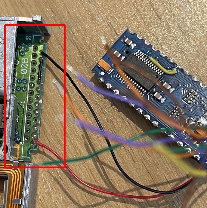
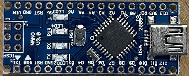
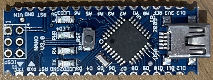
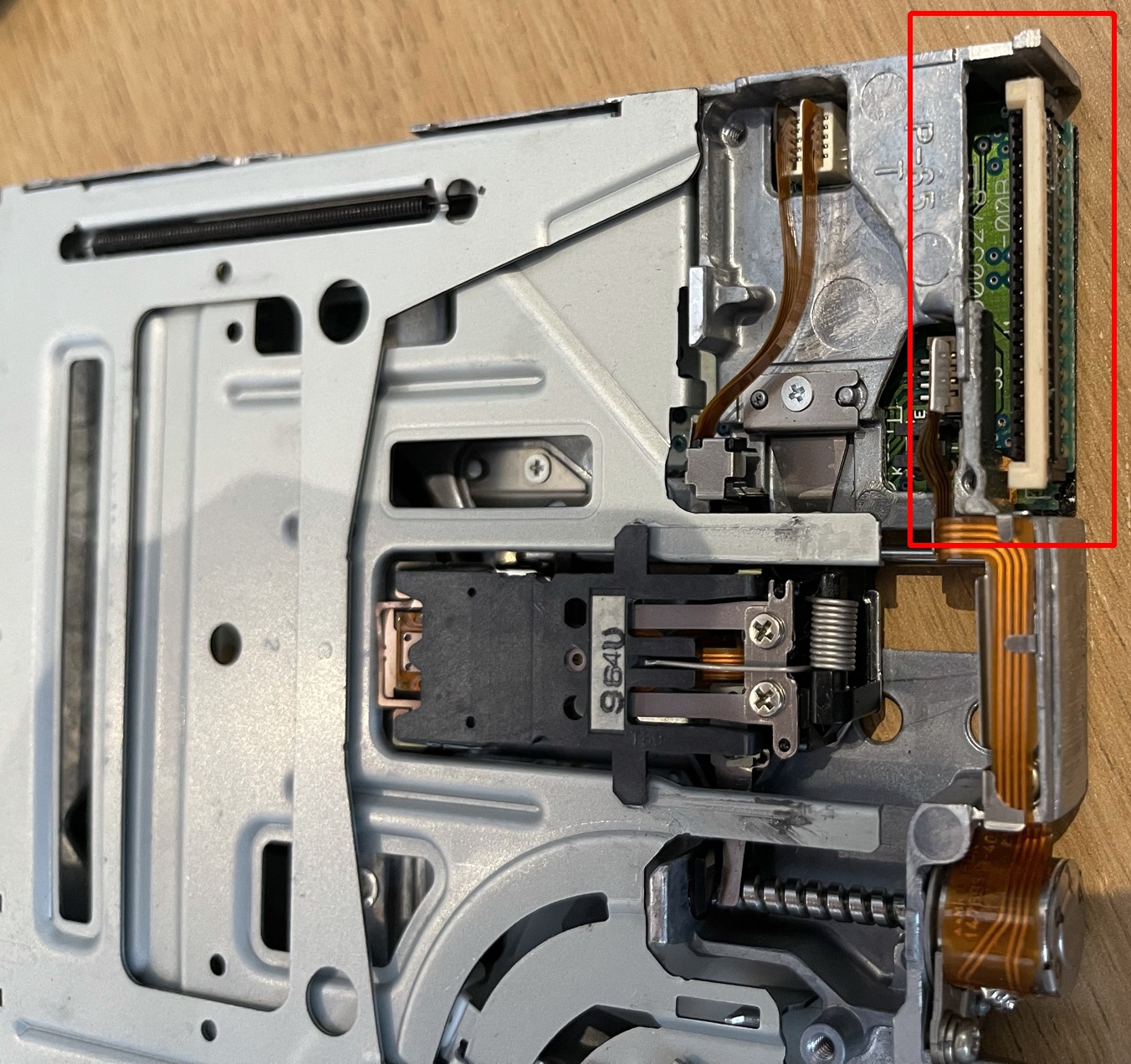
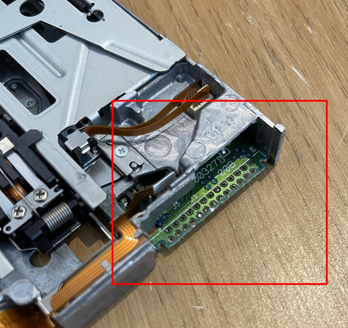
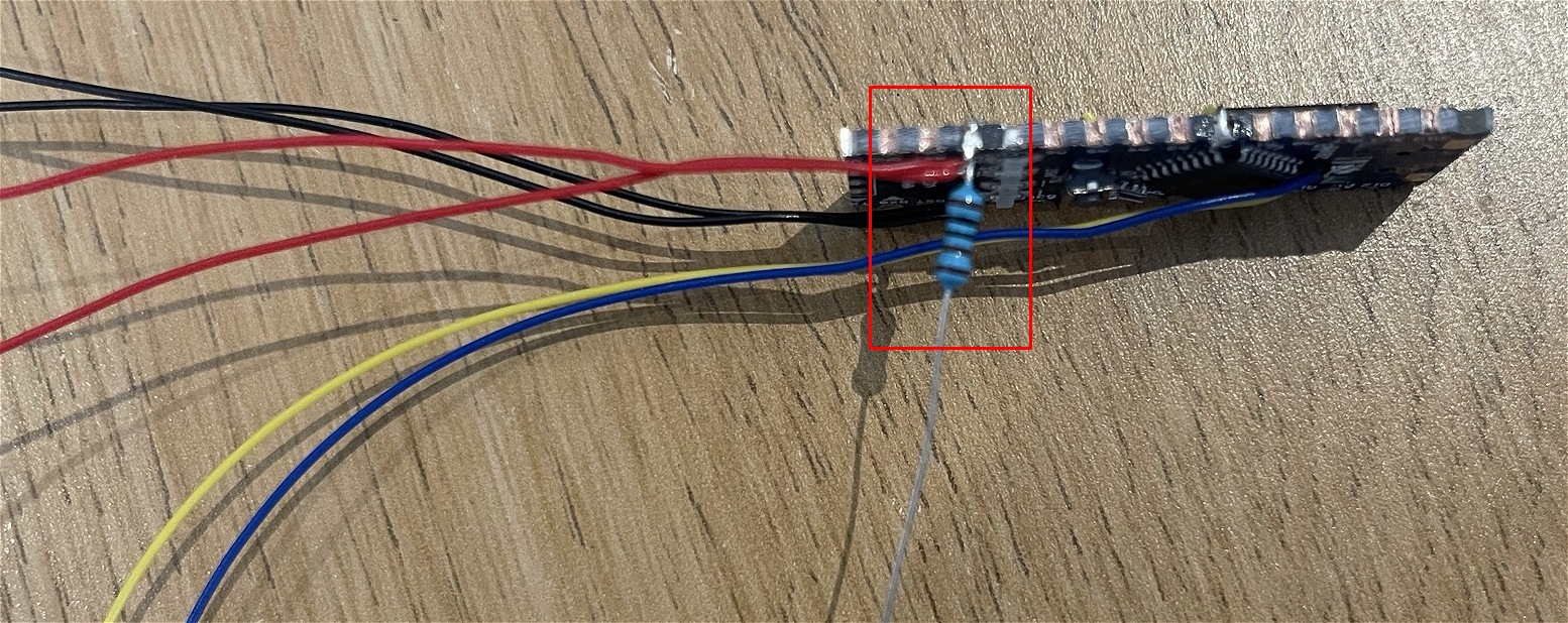
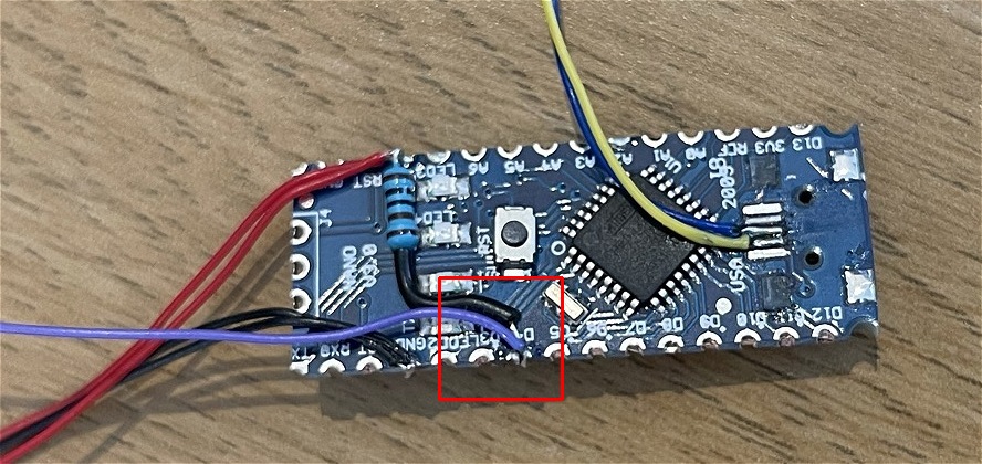
You need: A slimline Drive (More Information), an Arduino Nano (official) (or FTDI clone), a 1K resistor, Kapton tape, insulating tape, a soldering iron & solder, sandpaper, and some patienceNOTE: THIS Guide is for DrawBridge Classic. You will need to wire Pin 4 and 8 different for DrawBridge Plus


| Arduino | PC IDC | Slimline 26-pin FFC | PIN | PIN | |
|---|---|---|---|---|---|
| PIN | 34-Pin | Variant A | Variant B | Name | Code |
| 0 | already connected | ||||
| 1 | already connected | ||||
| 2 | 8 | 2 | 25 | Index | /INDEX |
| 3 | 22 | 16 | 11 | Write Data | /WDATA |
| 4 | 26 | 20 | 7 | Track 0 | /TRK00 |
| 5 | 16 | 10 | 17 | Motor Enable B | /MOTEB |
| 6 | 18 | 12 | 15 | Direction | /DIR |
| 7 | 20 | 14 | 13 | Step | /STEP |
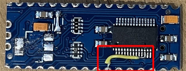
| 8 | 30 | 24 | 3 | Read Data * | /RDATA |
| 9 | 32 | 26 | 1 | Head Select | /SIDE1 |
| 10 | 34 | 6 | 21 | Disk Change | /DSKCHG |
| 11 | 12 | 4 | 23 | Drive Select B | /DRVSB |
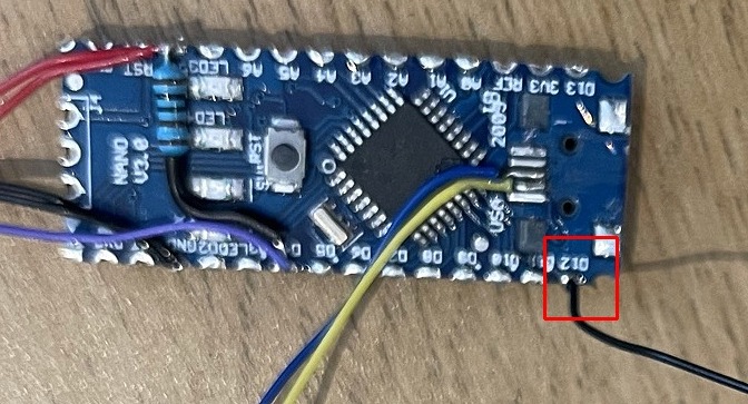
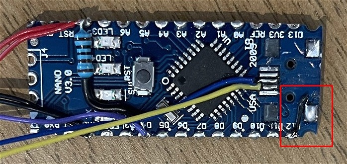
| 12 | Connect to GND | Enables DiskChange Support for WinUAE Using ISP? | |||
| A0 | 24 | 18 | 9 | Write Gate | /WGATE |
| A1 | 28 | 22 | 5 | Write Protect | /WPT |
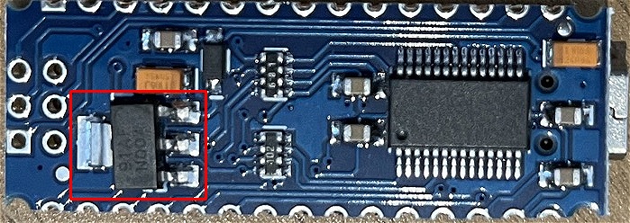
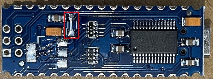
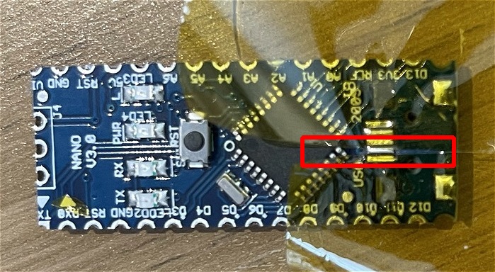
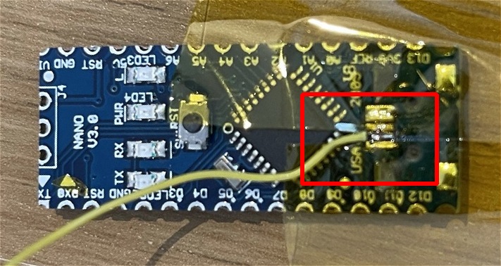
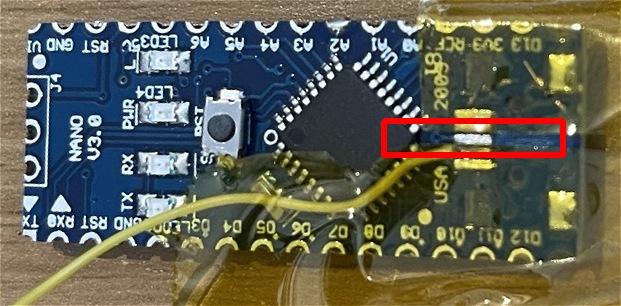
| A2 | CTS on FTDI on reverse (see above) | ||||
| A3 | 2 | 9 | 18 | Density Select | /REDWC |
| 5V** | 1,3,5 | 22,24,26 | 5V | ||
| GND | odd numbered pins | 15,17,23,25 | 2,4,6,8, 10,12,14,20 | GND | |